Lecture
The influence of external factors on reliability
The effect of heat and cold on electronic equipment.
The effect of moisture on electronic equipment.
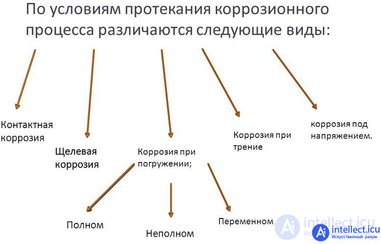
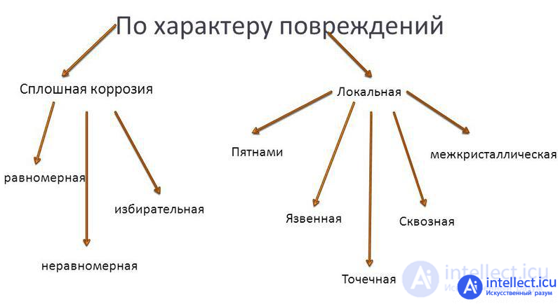
The effects of various types of corrosion on electronic components
The action of the biological environment on electronic components.
The effect of solar radiation on electrical radio equipment.
The effect of dust and sand on electronic equipment.
The action of mechanical loads on electronic components.
Effects of radiation on electronic components
The impact of electrostatics on electronic components
Aging and wear of electronic equipment materials.
Degradation changes in the parameters and characteristics of semiconductor elements
Classification of microcircuits by scope and working conditions in various environments
Literature
It is possible to correctly analyze the failures and find ways to improve the reliability of elements and systems, knowing the factors that affect reliability and the causes of failures. According to the nature of the impact, operational factors are divided into objective (impact of the external environment) and subjective (impact of staff). Objective factors can be divided into two groups: external and internal. External factors include influences depending on the external environment and the conditions of use of the devices: temperature, humidity, atmospheric and contact corrosion, biological environment, solar radiation, dust and sand, and mechanical influences. Internal changes should include all changes in the structure of materials and device parameters, i.e., all processes of natural aging and wear.
The subjective factors include the qualifications of the maintenance personnel and the organization of their technical training, the level of technological discipline of servicing devices, the organization of the collection and analysis of information about failures, the procedure for storage and transportation of equipment.
The reliability of the devices to a certain extent depends on the action of heat and cold. The temperature of the elements can change under the influence of sunlight, heating of equipment from nearby sources of high temperature, from internal sources. The temperature differences of the elements occur with a daily temperature change, the transfer of equipment from a heated room to an environment with cold air and vice versa, etc. Fluctuations in ambient temperature during the day are of great importance for the operation of the equipment. The maximum temperature difference during the day in one place is characterized by the following data: tropical climate plus 10 ° C, temperate regions plus 25 ° C, deserts plus 40 ° C. The maximum temperature in the shade in Russia is plus 50 ° C, and the minimum minus 50 ° C.
During the operation of the equipment, part of the electrical energy is converted into heat, so the temperature of individual elements can be significantly higher than the ambient temperature. The most heated cylinders of electron tubes, the temperature of which reaches plus (150-250) ° C. The lubricant in the code transmitters is heated to a temperature of plus 100 ° C.
There are three types of temperature effects: continuous, periodic and aperiodic.
Constant exposure to temperature is typical for equipment that continuously works indoors. Damage to the elements in this case is due to a mismatch between the permissible operating temperature of the element and the thermal effect. In addition, the equipment may fail due to accelerated aging of the elements (mounting wires, relay windings, lubricant, etc.), due to the high operating temperature and the lack of cooling means.
Periodic exposure may be due to daily temperature changes, regular sun exposure, etc. Temperature transitions through zero in the presence of moisture are especially harmful, which under certain conditions can lead to contacts becoming frosty, freezing of relay anchors, breaking contact in electric drives, etc. .
Aperiodic exposure is caused by a single exposure to heat or cold, for example, when equipment is removed from a warm room to cold or vice versa.
Heat and cold strongly affect the properties of metals in the equipment, which leads to a change in landing and installation gaps, weakening of the fastenings of parts and assemblies, displacement of parts relative to each other, the occurrence of significant stresses that cause deformation of parts, changes in electrical and magnetic parameters (resistivity and magnetic permeability).
The parameters of a number of elements are largely dependent on temperature. So, during operation, the capacitance of electrolytic capacitors only under the influence of temperature changes from minus 60 to plus 100 ° C can vary over a wide range. Depending on the temperature, the dielectric loss of capacitors, insulation resistance and dielectric strength change. The resistors used in the signaling equipment are very sensitive to temperature deviation, and their resistance can vary by 15-25% in the range from minus 60 to plus 60 cC.
Due to thermal expansion of parts and changes in the electrical properties of materials, the parameters of inductors change depending on temperature, which entails the departure of the resonant frequency of the circuit. Semiconductor diodes and triodes are more affected by temperature. When the ambient temperature changes from minus 50 to plus 60 ° С, their parameters change by 10-25%. So, due to changes in the parameters of semiconductor devices, the centralized dispatch code devices may fail to operate at a temperature of minus 40 ° С.
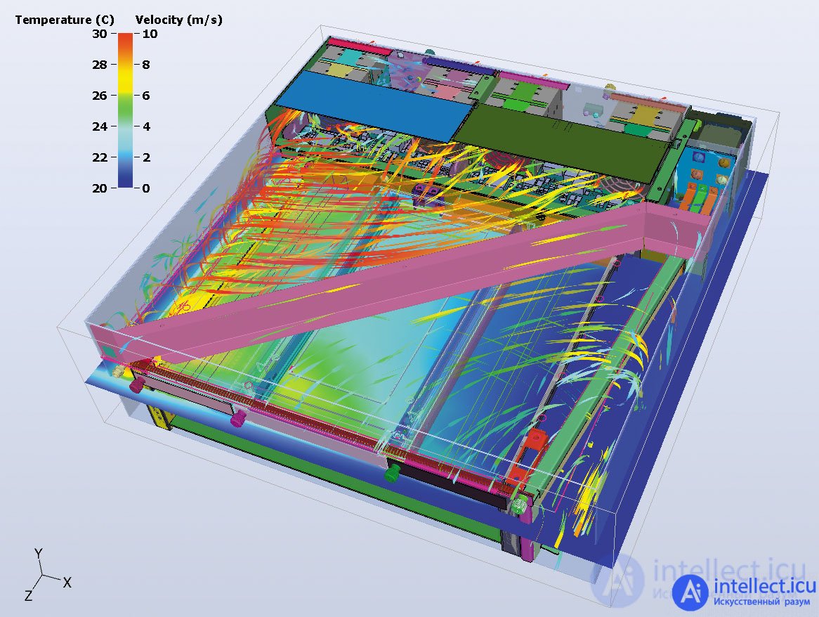
Fig. Temperature distribution in a three-dimensional model obtained using 6Sigma
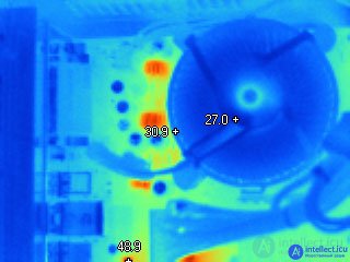
Heating the elements of the computer motherboard
Most components on the Raspberry Pi 3 Model B and Raspberry Pi 2 Model B boards have an industrial temperature range of -40 ℃ ... + 85 ℃. It is of practical interest to test the boards in a wider temperature range from -55 ℃ to + 110 ℃ and evaluate the limits of their performance.
The experimental setup is shown in Fig. 1. Raspberry Pi single-board computers were placed in the TCT-811 heat-cold chamber. RPi 2 connected to the LP-Link TL-WR720N router via Ethernet, and RPi 3 connected via Wi-Fi. Board power was supplied via USB adapters. Board management and data collection were carried out through SSH access from the operator’s computer.
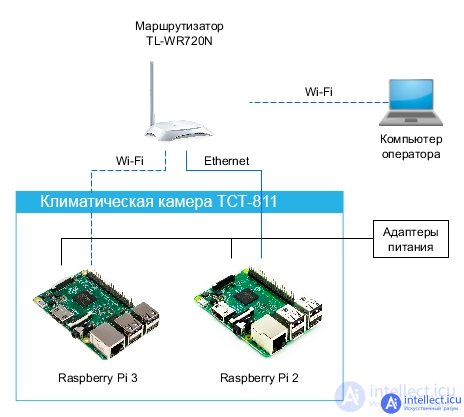
Figure 1. Scheme of the experimental installation of temperature testing
As an operating system, Raspbian was used as the main recommended and supported by the manufacturer. Performance testing was carried out using the SysBench utility - a modular, cross-platform multi-threaded application that allows you to quickly evaluate system parameters for work under high load. Test data was recorded on the internal memory of the board, and then, upon request, copied to the operator’s computer. As a data carrier, a QUMO 32GB Class 10 SD card was used.
To conduct the test, the boards were placed in a chamber and connected according to the circuit in Fig. 1. Then the algorithm for changing the temperature in the chamber was set. The camera was programmed for a stepwise increase in temperature, first from room temperature + 23 ℃ to + 110 ℃, then for quick cooling to room temperature and a further stepwise decrease in temperature to -50 ℃ (Fig. 2). A total of 19 measurement steps were implemented with a temperature step between steps of 10 ℃ (Table 1).
| Test Stage Number | 1 | 2 | 3 | 4 | 5 | 6 | 7 | 8 | nine | 10 | eleven | 12 | 13 | fourteen | fifteen | 16 | 17 | eighteen | 19 |
| The temperature in the chamber at the stage, ℃ | +23 | +30 | +40 | +50 | +60 | +70 | +80 | +90 | +100 | +110 | +106 | +27 | -20 | -25 | -thirty | -35 | -40 | -45 | -fifty |
At each stage of testing, the appropriate temperature was first set in the chamber, then the boards were kept at this temperature in the off state for about 6 minutes. Then the boards turned on almost simultaneously, on each the Sysbench test was launched, and in addition the temperature of the processor was measured. After the tests were completed, the boards were turned off and re-aged for 1-2 minutes at the same temperature before the camera proceeded to the next stage. The rate of temperature change between stages was approximately 1 ℃ / min.
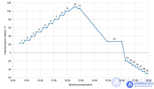
Figure 2. Changing the temperature in the chamber during the tests.
Each complete step of passing the Sysbench test consisted of the sequential launch of three modules: a processor test, a memory test, and a stream test. The result of each Sysbench module was the determination of its execution time in seconds. Let us describe in more detail each of the tests.
Processor test (--test = cpu) Sysbench uses 64-bit integers to calculate primes up to the value specified by the --cpu-max-primes parameter. It is also possible to specify several threads, but we used the default value - one thread.
A memory test (--test = threads) allocates a memory buffer and performs read or write operations. The amount of data read or written in one operation is determined by the size of the pointer 32 or 64 bits. The process repeats until the specified volume is processed (--memory-total-size). It is possible to set the number of threads (--num-threads), the buffer size (--memory-block-size), and the type of operation (read or write --memory-oper = [read | write]).
The thread test (--test = memory) checks the processor in a large number of competing threads. The test is to create multiple threads (--num-threads) and multiple mutexes (--thread-locks). Next, each thread begins to generate requests that block the mutex, perform processor tasks (to simulate real work), and unlock the mutex. For each request, lock-execute-unlock actions are performed several times, the number of which is specified by the --thread-yields parameter.
The abbreviated text of the bash script for starting Sysbench modules with the corresponding parameters is shown below:
for count in {1..5}
do
sysbench --test = cpu --cpu-max-prime = 1150 run
sysbench --test = memory --memory-block-size = 1M --memory-total-size = 10G run
sysbench --num-threads = 64 --test = threads --thread-yields = 1000 --thread-locks = 8 run
vcgencmd measure_temp
done
The processor temperature in degrees Celsius was derived from its built-in sensor. The readings of the built-in temperature sensor were carried out by the vcgencmd measure_temp command.
Sysbench test results are shown in Figure 3 . At each stage, the Sysbench test was repeated sequentially 5 times, performance data were averaged over the results of 5 tests. The processor temperature values are taken to be the maximum ones measured at each stage.
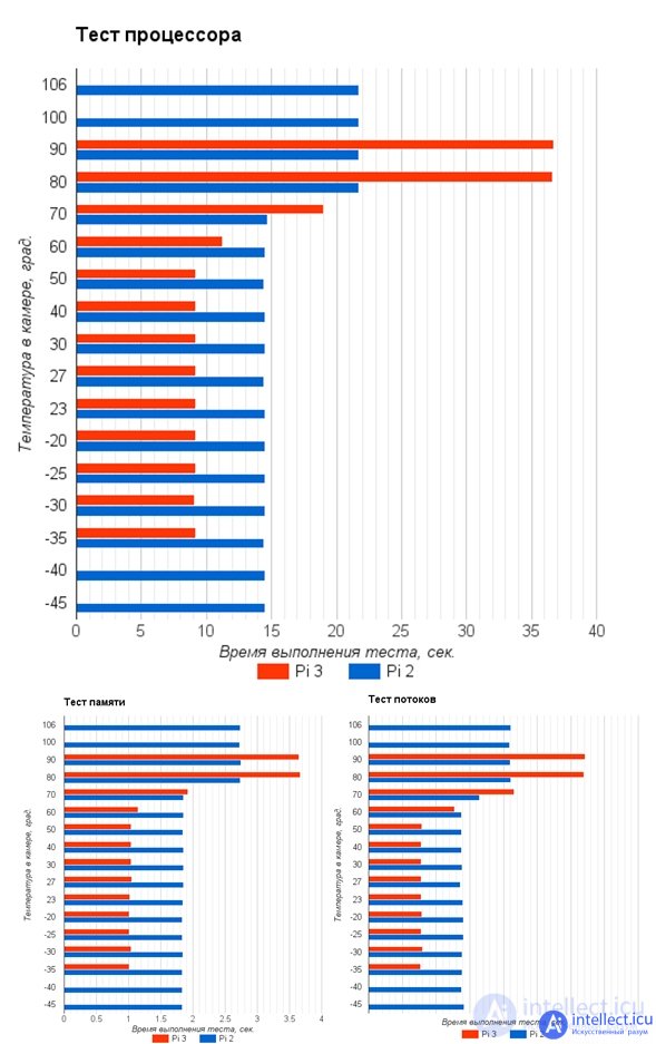
Figure 3. Sysbench test results on Raspberry Pi 3 and Raspberry Pi 2 single-board computers
Figure 3 shows that the performance picture on all three tests is almost the same for both RPi 3 and RPi 2. In the temperature range from -35 ℃ to + 50 ℃ RPi 3 is approximately 1.6 times faster than RPi 2, which is consistent with official performance tests [4]. When the temperature threshold of the processor specified in the configuration files is reached, the default is + 85 ℃, the mechanism for protecting the processor from overheating due to skipping machine clocks — throttling clocks or throttling [8] is started.
Computers stopped starting at different temperatures: RPi 3 at temperatures above + 90 ℃, and RPi 2 at temperatures above + 106 ℃. At temperatures below 0 ℃, there is no change in performance for both boards. At temperatures below -35 ℃ the RPi 3 board and temperatures below -45 ℃ the RPi 2 board will not start. Both at high and at low temperatures, the boards resumed their operability after unloading - and returning to the operating temperature range.
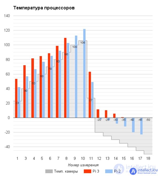
Figure 4. Temperature of the Raspberry Pi 3 and Raspberry Pi 2 processors at different ambient temperatures in the test chamber.
The temperature values in the test chamber and the corresponding temperatures of the RPi 2 and RPi 3 board processors are shown in Figure 4. Since the RPi 3 processor heats more than the processor RPi 2, the throttling threshold temperature of + 85 ℃ in it is reached at + 50 ℃ of the environment, while RPi 2 starts throttling at a temperature of + 70 ℃. Therefore, in the test results we see that at temperatures above + 50 ℃ RPi 3 is inferior to RPi 2 in performance. At these temperatures, it is recommended to use processor cooling [8].
In the tests, RPi 3 boards started up and ran in the temperature range from -35 ℃ to + 90 ℃, and RPi 2 boards ranged from -45 ℃ to + 106 ℃. These ranges are close to the industrial temperature range of the used electronic components -40 ... + 85 ℃.
The study does not pretend to be complete and unconditional engineering recommendations. The following conditions and circumstances influenced its results. First of all, SD memory cards caused problems, which often caused malfunctions, they had to be reformatted and the system image re-recorded to restore the cards. Secondly, the comparability of the test results of the RPi 2 and RPi 3 could be affected by different ways of communicating with the boards: RPi 2 over Ethernet, and RPi 3 over Wi-Fi. Thirdly, the test parameters were chosen in such a way that the total test time fit into the period of one working day, so we can not judge whether the boards remain operational under longer exposure to temperatures. Fourth, the tests were not carried out in a certified center and not in strict accordance with GOST,although the applied methodology was developed on the basis of the standards GOST 28199-89 “Basic test methods for exposure to external factors. Part 2. Tests. Test A: Cold ”and GOST 28200-89“ Basic test methods for exposure to external factors. Part 2. Tests. Test B: Dry Heat. ”
The complexity of printed circuit boards is constantly increasing, and, consequently, the risk of failures caused by the thermal conditions of electronic devices increases.
The work of tens of millions of transistors that form integrated circuits (ICs) is inextricably linked to power losses. The heat generated in this case heats the crystal and is partially removed through the housing of the microcircuit. Exceeding the maximum temperature leads to the fact that the IC begins to work incorrectly or even completely fails.
To limit power losses and reduce overheating, the developers reduce the operating voltage and reduce the area of the crystal. However, a decrease in crystal size also means that the transistor density increases. Thus, although the crystal as a whole is not so hot, local heating of the active zones can be significant. To protect against local overheating, it is necessary to implement effective cooling methods. If the heat dissipation is not performed and is not properly controlled, this leads to a reduction in the service life of the microcircuit and even to its failure.
After turning on the power, the temperature of the IC crystal rises until thermal equilibrium with the environment is reached. The value of the steady-state operating temperature affects the time between failures. In practice, the rule of thumb is often used, according to which at each increase in the temperature of the crystal by 10 ° C, the failure rate for this component is doubled. Thus, lowering the temperature by 10 ... 15 ° C can double the life of the device. Accordingly, developers must consider the value of the operating temperature, as well as the safety margin of the device.
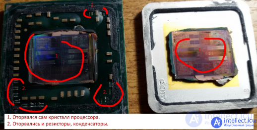
CPU overheating
Among discrete passive components, capacitors are most sensitive to temperature rise. The lack of compact and thermostable large capacitors is one of the most significant obstacles in the development of high-temperature applications.
For traditional ceramic dielectric materials, there is a clear connection between permittivity and temperature stability. The capacitance of C0G or NP0 capacitors made of materials with a low dielectric constant remains almost constant with temperature and changes little over time. Capacitors made of materials with high dielectric constant, for example, X7R, are characterized by high capacity with compact dimensions. However, the capacitance value for them is highly dependent on temperature. In addition, the leakage currents for the X7R also increase with increasing temperature, which makes it difficult to charge capacitors.
Unfortunately, there are not many alternatives. For example, standard lavsan film capacitors cannot be used at temperatures above 150 ° C due to mechanical damage and breakdown.
Some polymeric materials, in particular fluoroplast, retain mechanical and electrical resistance at higher operating temperatures. They are characterized by a minimal change in dielectric constant and insulation resistance even after 1000 hours exposure at 250 ° C. However, such films have a very low dielectric constant. In addition, the manufacture of thin films is difficult. All this significantly reduces the specific capacity of polymer film capacitors.
As a result, when creating high-temperature applications, the best option is to use batteries of thermostable ceramic capacitors. In addition, new ceramic dielectric materials exhibit improved temperature stability through the use of microstructuring or special materials with barium titanate impurities. Currently, the most promising material is X8R, which has a specific capacity at the level of X7R, but is characterized by a minimal change in capacity with increasing temperature up to 150 ° C.
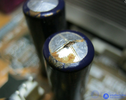
Rice destruction of electrolytic capacitor due to overheating
When current flows, thermal energy is inevitably released, for this reason, self-heating of resistors is normal. The effect of temperature on the parameters of resistors depends on the design and is characterized by a temperature coefficient of resistance.
The temperature coefficient determines the dependence of resistance on temperature. It can be both positive and negative. As a rule, composite resistors have a negative temperature coefficient, and metal film and wire resistors are characterized by a positive temperature coefficient. This means that the resistance of composite resistors decreases with temperature hanging, and the resistance of metal film on the contrary increases.
A low temperature coefficient indicates that the resistance is weakly dependent on temperature. High-quality resistors have a low or even zero temperature coefficient, which is extremely important for precision and measuring circuits.
Composite resistors are most often found in electronic circuits. In them, the resistive material is molded in the form of a small rod or deposited on an insulated core. Coaxial wire leads are connected from different ends of the component. Outside, the resistor is coated with bakelite to provide insulation. The resistance rating is usually color coded according to the EIA.
Standard resistance values range from a fraction of Ohm to several megohms. Precise manufacturing of resistances with a small error is difficult, however, this, as a rule, is not required. Usually used accuracy of 5 and 10 percent. Based on these tolerances, standard series of ratings are calculated in which the resistances of the resistors of adjacent ratings do not overlap even with a maximum error. Precision resistors also exist for applications requiring extremely high accuracy. They use pure carbon (with a minimum amount of impurities of less than 1%) as a resistive material, which is placed in a spiral groove on a ceramic rod.
The rated power of the output resistors lies in the range from 1/4 W to 2 W. The higher the power of the resistor, the larger its dimensions. There is a useful rule for choosing power, according to which, to ensure stable and reliable operation, the actual dissipated power of the resistor should not exceed 50 percent of the nominal value. Do not forget that power is dissipated in the form of heat, and excess heat leads to a decrease in resistance due to the negative temperature coefficient of composite resistors.
Overheating can damage the resistor. For this reason, caution should be exercised when soldering. In addition, excessive heating leads to a change in color of the resistor body and color code bands.
Speaking of sizes, it is worth noting that the dimensions of precision resistors vary from manufacturer to manufacturer. This is often misleading, because the dimensions of precision resistors are usually larger, which is the case for resistors with standard tolerances. However, they cost several times more.
As mentioned above, the resistance of wire resistors increases with heating. This change is small enough. Nevertheless, caution should be exercised and minimal overheating to obtain stable resistance. Resistors must be installed in places with free air circulation and have a double power margin. In other words, if the calculations show that the dissipated power is 5 watts, then a resistor with a rated power of 10 watts should be chosen. Although this rule is more important for composite resistors that are sensitive to overheating, it should be observed in the case of wire resistors.
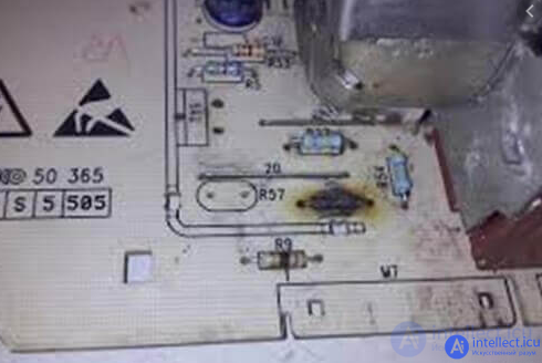
Destruction of a resistor due to overheating
Printed circuit boards (PCBs) and substrates (aluminum, ceramic, etc.) play the role of the structural base, carry out heat dissipation and electrically connect electronic components. However, when a certain temperature limit is exceeded, they lose their working capacity. For example, in printed circuit boards based on fiberglass, the impregnating compound becomes fluid at the glass transition temperature, and the board itself is deformed due to the strong heterogeneity of the thermal expansion coefficients along different axes. These changes lead to peeling of copper conductive paths and deterioration of the insulating properties of PP.
As mentioned above, printed circuit boards perform the function of heat dissipation. Standard PP based on fiberglass FR-4 have a glass transition temperature of less than 135 ° C, although there are high-temperature versions with operating temperatures up to 180 ° C. Boards based on bismaleimide triazine (BT), cyanate polyester (CE) or polyimide materials can be used at temperatures up to 200 ° C or even higher. Quartz-polyimide boards remain operational up to 260 ° C. Boards made of fluoroplastic (PTFE) have a glass transition temperature Tg of more than 300 ° C, but they are not recommended for use at temperatures above 120 ° C due to poor adhesion of copper. The presence of a copper layer significantly improves the thermal characteristics of the printed circuit board, since its thermal conductivity is 1000 times higher than, for example, the "bare" FR-4.
A well-thought-out layout of the printed circuit board with a competent distribution of the most warming elements allows you to achieve excellent results without any additional cost. The use of copper landfills and massive contact pads to remove heat from the components, as well as the use of metallized holes and solid copper layers helps to significantly reduce thermal resistance.
Integrated circuits are becoming faster and more powerful, and the size of printed circuit boards is reduced. Modern compact PCs (for example, in smartphones and tablets), as well as high-performance electronic components require more efficient cooling compared to their predecessors. This is due to the fact that an increase in the density of the arrangement of the components leads to an increase in the specific generated power, which is why the electronics have to work at elevated temperatures. As a result, developers are forced to put more effort into ensuring quality heat dissipation.

Rice Overheating and destruction of the printed circuit board
Structural materials in most cases are used at temperatures not exceeding half the melting point. However, surface mounting technology suggests that solder will provide not only electrical contact, but also mechanical support at temperatures well above this reference point.
Heating the eutectic solder to 100 ° C corresponds to 80% of the melting temperature, and the yield property begins to appear. Above this temperature, shear strength decreases to an unacceptable level. In addition, when heated, the risk of the formation of copper-tin intermetallic compounds increases, which leads to an increase in the fragility and fatigue of soldered joints. There are solders that retain their mechanical properties at temperatures up to 200 ° C.
Currently, to reduce the impact of lead on the nature and health of people, an active transition to lead-free technologies is underway. At the same time, such a transition leads to a number of problems with the reliability, manufacturability, availability, and ultimate cost of electronics. The fact is that in terms of mechanical, thermal, electrical and technological properties, most of the materials and alloys offered are inferior to lead-tin (Pb-Sn) solder. During installation, lead-free solders require a higher melting point, about 260 ° C, while for traditional Pb-Sn solders, the melting point is 245 ° C. Additional heating significantly increases the likelihood of damage to components and PCB during installation. In addition, the cost of lead-free solders is higher.To date, the transition to lead-free technology has not been completed.
Summing up for this section, it can be noted that the overheating of the electronic device is limited to the lowest of the permissible temperatures for the components used, including the printed circuit board, solder, electronic components (connectors, ICs, passive elements, etc.).
Part of the heat from the components is removed due to air convection. However, during operation, the air itself begins to warm up. If there is no ventilation in the case of the electronic device, then the temperature will constantly increase, which means that the efficiency of heat removal from the components will decrease.
Performing thermal analysis during the design process of the electronic device allows you to optimally place the components and, thereby, prevent the occurrence of problems with cooling. This, in turn, minimizes or completely eliminates the need for costly changes made at the final stages of development. Modern electronic devices consist of many elements, such as printed circuit boards, fans, vents, partitions, electromagnetic radiation screens, filters, cables, power supplies, etc. These elements further complicate thermal analysis. Currently, there are automated design systems that help developers cope with the complex task of thermal modeling.These software tools provide a user-friendly graphical tool and allow quick and accurate calculations.
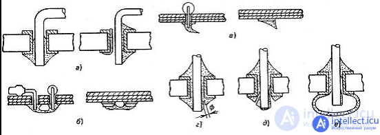
Fig. Types of defects of soldered joints:
a - nepropaya; b - jumpers; in - icicles; g - pores; d - cracks; e - influx
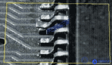
Fig. Technological defect associated with violation of the coplanarity of the conclusions of the integrated circuit
Deterioration of electrical contact can also be the result of cracking initiated by mechanical stresses when thermal expansion coefficients do not match, which is eliminated by a decrease in the temperature gradient between the board and components. Excessive formation of intermetallic compounds at the interfaces of soldered joints can also cause poor electrical contact, for example, when soldering the leads of components on a board with an aged coating [3].
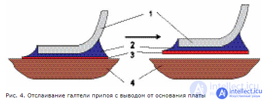
A special case of the lack of electrical contact is the peeling of the fillet of solder and the contact pad from the base of the printed circuit board. In fig. Figure 4 schematically shows the soldered connection of terminal 1 of the electronic component before and after peeling off the fillet 2. This often occurs when soldering deformed terminals. In the process of solder crystallization, this mechanical stress created by deformed leads behaves like a spring under tension. The heating of the board during soldering significantly reduces the adhesion strength of the contact pad 3 to the base of the board 4, and this leads to the peeling of the fillet of the solder from the board.
Humidity characterizes the amount of moisture in the air. Separate absolute and relative humidity. Absolute humidity determines the mass of water vapor per unit volume of air. It is measured in grams per cubic meter (g / m3). Relative humidity is the ratio of absolute humidity to theoretical maximum at a given temperature and pressure. Relative humidity is expressed as a percentage. Thus, if air retains half the moisture from the maximum amount, then relative humidity is 50 percent.
The damaging effects of humidity on electronic equipment are often underestimated. The effects of moisture are dependent on the materials used.
High humidity can cause direct damage to electronics, for example, in the form of gluing printed circuit boards. In addition, the negative effects of humidity can be implicit. In particular, increased humidity is a factor contributing to corrosion.
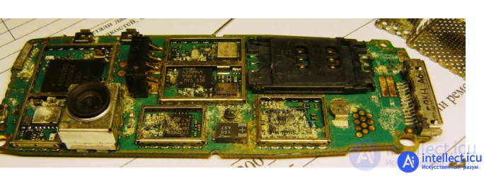
A certain percentage of failures is caused by the action of moisture on the materials and elements used in the equipment. Water vapor in the form of tiny particles in the surrounding air can affect. Elements of the equipment can directly come into contact with water droplets or water during condensation of water vapor on the surface of the equipment, when wetted by splashes of water or rain, ingress and melting of snow.
Moisture changes the electrical characteristics of materials, promotes their hydrolysis, accelerates the aging process, causes intense corrosion of metals, promotes the formation of mold, etc. In different geographical areas, relative humidity varies widely (5-95%).
The mechanical and electrical properties of metals, if we exclude the phenomenon of corrosion occurring under the influence of moisture, are practically not affected by changes in air humidity and moisture condensation. But in dielectric materials, mechanical and electrical characteristics change under the influence of moisture. Some materials with bulk hygroscopicity, when absorbed by moisture, increase their linear dimensions, which is why internal stresses increase, gaps and landing dimensions change, warping occurs, etc. Moisture has an even greater effect on the electrical characteristics of dielectrics. The penetration of moisture into the pores of the dielectric significantly increases the dielectric constant, which causes, for example, a corresponding change in the capacitance of the capacitors. Moisture absorbed by the insulating material,reduces breakdown voltage and increases the dielectric loss tangent.
The presence of moisture leads to the following characteristic changes in the parameters of the equipment elements:
To ensure the moisture resistance of materials to equipment elements, the following measures can be recommended: the use of non-hygroscopic insulation materials, coating of parts and assemblies with non-hygroscopic and hydrophobic materials (plastics, varnishes, paints, etc.), galvanic or paint coating of metal surfaces, and sealing of individual elements of the equipment ( transformers, relays, chokes, relay cabinets, etc.), impregnation of parts and assemblies with non-hygroscopic materials, introduction of ambient wetting agents to the equipment hoteliers.
Of these measures, special attention should be paid to the use of desiccants. Silica gel (SiO2) can absorb up to 60% of its own weight in water. Moisture adsorbed by silica gel is firmly held; to remove it, heating of silica gel to a temperature above plus 500 0 C is required. The use of silica gel is also convenient because it changes color as moisture is absorbed, making it easy to control its state.
Degradation. Humidity reduces the effectiveness of infrared equipment and also degrades the properties of some materials, such as fabrics, some plastics, and cellulose.
Putting up. High humidity leads to sticking (delamination) of cheap printed circuit boards.
Deformation. The presence of increased humidity can cause not only deformation, but also swelling of fibrous materials.
The destruction of fibrous materials. Fibrous materials with high hygroscopic properties when exposed to moisture impair tensile strength and experience significant deformations.
Surface resistance. The presence of moisture reduces surface resistance. In turn, a decrease in the surface resistance of a printed circuit board can affect the characteristics of precision timing circuits (which leads to a change in the frequency of the generator), bypass the output current of the current source, lead to loss of sensitivity or reduce the input resistance of high-impedance amplifiers.
Migration of metals. The process of electrolytic transfer of metal ions (metal migration) occurs between closely spaced conductive metal conductors in the presence of moisture and potential difference (Fig. This is evidenced by the site https://intellect.icu. 2, Fig. 3). Migration is especially characteristic of silver. The presence of metal migration leads to a decrease in insulation resistance, an increase in leakage currents, and even to the occurrence of catastrophic short circuits. Metal migration is a common cause of chip failures.
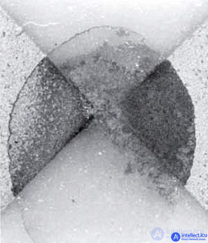
Fig. 2. Experience in the study of metal migration in the presence of water. For a silver-platinum thick-film conductor, a short circuit occurs after 25 minutes when a 4 V DC voltage is applied
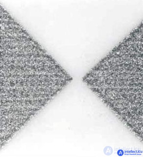
Fig. 3. Experience in the study of metal migration in the presence of water. For a gold thick-film conductor with a voltage of 4 V after 1 hour, metal migration is not observed
Pore formation due to gas evolution from PP materials. During the installation of components in soldered joints, cavities and pores may appear that arise due to gas evolution. Such phenomena create a lot of problems:
The lack of proper purity in the manufacture of electronic devices can be an additional reason for the deterioration of electrical characteristics. Consider the main sources of pollution that can cause the failure of electronic devices during long-term operation.
PCB manufacturing. Contamination can occur during the production of PP and is usually the result of incomplete curing of the resin or poor-quality application of a solder mask.
Flux residues. The input impedance of devices can change when exposed to moisture accumulated in the flux residue on the PP. When using manual soldering, some modern non-washable synthetic fluxes do not reach the decontamination temperature. With prolonged exposure to high humidity, a white organic salt deposit occurs at the site of the flux residues, which, although it does not have significant conductivity, can nevertheless trap moisture. This in turn affects surface resistance. In addition, this salt deposit is an ideal medium for the migration of metals.
Electrolytic corrosion. Corrosion usually requires moisture and soluble impurities that may be present both on the surface of materials and in the surrounding air. Together, moisture and impurities form the electrolyte necessary for the electrochemical reaction - corrosion. The reaction occurs if dissimilar metals are in direct contact or the cavities between them are filled with electrolyte. Moreover, the presence of visible moisture is not necessary for corrosion; an ultrathin water film will be sufficient.
The presence of a potential difference and a conductive electrolyte on the surface of the PP also contributes to the delamination of metal conductors and the migration of metals, which in turn leads to short circuits.
Moisture in the connector corrodes the contacts. As a result, the resistance of the electrical connection increases, and the contact itself heats up. If the temperature rises significantly, a fire may occur.
Low humidity can also be a problem. This primarily applies to hygroscopic materials, which, when moisture is removed, become deformed, become brittle, and lose weight and volume.
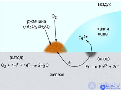
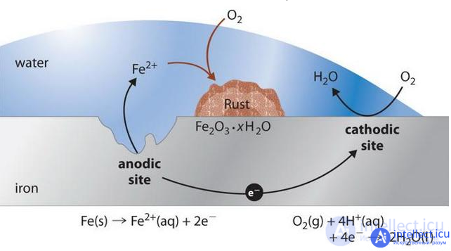
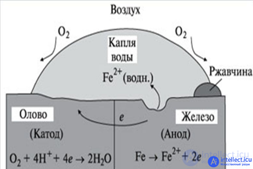
Rice Electrochemical Corrosion Mechanism
The process of electrochemical corrosion depends on the chemical composition of the materials and the characteristics of the external environment.
If the so-called technical metal is covered with a wet film, then in each of these galvanic microelements that are formed on the surface, two independent reactions occur.
The more active component of the corrosive pair gives up electrons (for example, zinc in a Zn-Fe pair) and passes into the liquid medium as hydrated ions (that is, corrodes) by the following reaction (anode process):
Thus, the presence of oxidizing agents in the water film, which are able to bind electrons, provides the possibility of further progress of the anode process. Accordingly, electrochemical corrosion can develop only if both the anodic and the cathodic processes occur simultaneously. Due to the inhibition of one of them, the oxidation rate decreases.
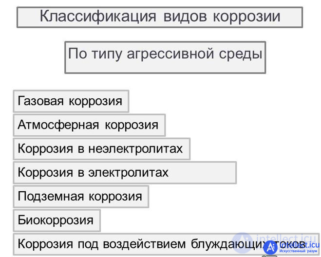
Atmospheric corrosion can affect the operation of the equipment, which happens: wet, which occurs when the relative humidity is close to 100%, or when water drops directly fall on the elements of the equipment; moist, flowing under a thin, sometimes invisible layer of liquid formed at a relative humidity of less than 100%; dry, occurring without condensation of moisture on the surface.
The corrosion rate depends on the relative humidity of the air, as well as on the degree of air pollution and the surface of the components. Corrosion is associated with the formation of a moisture layer on the surface of elements. When this layer is contaminated with various chemical elements, salts, acids, always in the air, it turns into an electrolyte, accelerating the process of destruction of equipment elements.
Dry atmospheric corrosion proceeds in the form of growth on the surface of an element of an oxide film and can be explained by counter diffusion of metal ions and oxygen atoms or ions. An example of dry atmospheric corrosion is the tarnishing of the silver surface of the contacts of the plug relays. In this case, the surface (transient) resistance of the contacts increases.
Corrosion protection is reduced to the application of anticorrosive metal or paint coatings, the use of sealing or desiccants, and sometimes to the periodic removal of the oxide film formed as a result of dry atmospheric corrosion.
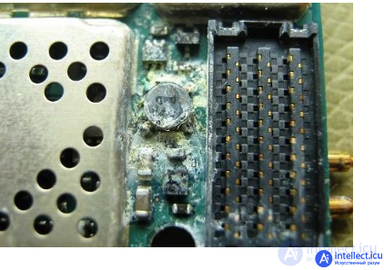

Rice impact on electronic components of deep electrochemical corrosion
Contact or electrolytic corrosion is a consequence of the contact of metals having various electrochemical potentials, in the presence of a conductive film of water between them. The resulting electrochemical micropair, in which a metal with a more negative potential plays the role of a cathode, leads to intensive destruction of the latter.
The effect of corrosion increases with increasing relative humidity. Contact corrosion becomes much greater if an electric current flows through the contact points of various metals due to the electrical circuitry of the equipment (contact petals, relay contacts, connectors, etc.). In the relay contacts, the effect of electrical destruction is aggravated by erosion - the physical destruction of contacts. Contact corrosion also includes the intense destruction of certain metals when they come in contact with certain types of wood species. So, iron, steel, aluminum and lead are intensively corroded in contact with oak, chestnut and some other species.
The fight against electrolytic corrosion is carried out primarily by careful selection of structural materials. In this case, it is always necessary to select pairs with the smallest potential difference. The acceptable value of the potential difference is considered to be 0.5 V (absolute value) for mid-latitudes and 0.25 V for equipment designed for operation in marine and tropical climates. In those cases when the selection of materials does not preclude contact corrosion, resort to galvanic coatings (nickel plating, chromium plating, silvering, gilding, etc.).
Drawing mechanism of contact corrosion
Particles of alloys of materials, such as brass, can vary in chemical composition. If an electrolyte is added, an electrical voltage arises between the individual particles (crystals). The crystals of the metal of the negative pole dissolve. Such corrosion can be distributed evenly over the surface or be pitted (funnel-shaped craters appear in place).
Many objects are subject to corrosion processes, beginning with the supporting structures of electronic equipment, element housings and contacts, printed circuit board elements and much more.

Methods of anti-corrosion - Galvanizing, phosphating, thermal spraying, alloying, electrochemical protection, non-metallic coatings (for example, varnish or enamels on a printed circuit board)
The biological environment includes fungal formations (mold), insects (beetles, termites, ants), rodents (rats, mice, etc.). The greatest damage to the equipment is caused by mold. It can develop on metals, glass and ceramics. In this case, a nutrient medium is a layer of dust (microorganisms) covering the surface of the materials. The destructive effect of mold is manifested in the form of: changes in the mechanical and electrical properties of materials that serve as a nutrient medium for the development of mold; corrosion of metals under the action of organic acids secreted by mold (citric, carbonic, oxalic, etc.); changes in the optical properties of materials. In addition, mold-covered equipment, even if it is working properly, naturally does not inspire confidence in the operating staff. Protection against mold is carried out by the selection of materials,not a breeding ground.
Along with mold, serious damage to the equipment is caused by termites and some types of ants. Termites penetrate the equipment and eat wood products, plastic, leather, etc. Some types of beetles that bury themselves in the ground and, bumping into the cable, violate its sheath, should also be considered harmful insects. Cables and wires (installation) are often damaged by rodents, especially often wires and cables in a vinyl sheath or rubber insulation. The main protection measures against insects and rodents are mechanical protection of equipment and cables, as well as the use of pesticides.
During operation and during storage in the open air, direct sunlight acts on the equipment. The long-wavelength part of the sun's rays transfers thermal energy, which contributes to an increase in temperature inside relay cabinets, blocks, etc. The short-wavelength part of the solar spectrum (violet and ultraviolet) is the main factor in the photochemical effect that leads to the oxidation of organic materials, changes in their properties, fading, and destruction of colors and etc.
Under the influence of sunlight, the decay of polyvinyl chloride, fluoroplastic, polyvinyl chloride, and plastic is sharply enhanced. Natural rubber and rubber harden and crack under the influence of sunlight. Also, under the influence of sunlight, paint coatings crack and collapse, losing their protective properties. The main ways to combat solar radiation are to create a microclimate in the equipment, the selection of materials.
Dust and sand, penetrating into the equipment and settling on the surface of the elements, can have a negative impact on its performance. On the one hand, dust and especially sand, due to its abrasive effect, contribute to the rapid wear of moving parts of the equipment. On the other hand, sand and dust are sufficiently hygroscopic. Therefore, the dust layer can be a good enough conductor, which will lead to a violation of the operating mode of the equipment.
Dust and sand, deposited on the contacts of relays and switches, often lead to the formation of an electric arc and a non-conductive layer between the contacts. Particularly often, equipment with printed circuitry of elements can fail, because due to the small distance between the parallel conductors, the dust causes a sharp drop in resistance between them.
It should be noted that dust of organic origin is a good environment for the development of mold. Therefore, without dust control, the above methods of combating fungal formations do not give the desired effect. Of the measures against dust and sand, the most effective is the creation of dustproof enclosures (relay cabinet, battery well, blocks, devices, etc.). However, the creation of such cases greatly complicates the heat sink. A necessary measure of maintaining reliability under operating conditions is the periodic cleaning of equipment from dust.
Mechanical loads on the equipment occur during storage, transportation and operation and are divided into two types: shock and vibration.
As a result of a shock, damped oscillations at the natural frequency occur in the apparatus. The designs as a whole and their individual elements are subject to these vibrations. The amplitude of the oscillations can be significant, which leads to fracture of brittle parts, wire breakage, destruction of rations, deformation of flexible materials, etc.
Vibration is a long alternating motion caused by external forces. The result of vibration can be breakdown of parts, wire breakage, misregistration, etc.
In general, mechanical loads on the equipment can cause devices to pop out of their sockets, weaken screw and rivet joints, break wires in places of bends, solders, etc., deform and break parts, break capacitors, resistors and semiconductor devices attached to their own
продолжение следует...
Часть 1 The influence of external factors on the reliability of electronic equipment and components - heat,
Часть 2 Effects of radiation on electronic components - The influence of

Подробнее о диагностике и поиске неисправностей
https://intellect.icu/testy-i-sovety-po-proverke-i-diagnostike-neispravnostej-radioelementov-diodov-tranzistorov-kondensatorov-termistorov-i-optopar-3260
Здесь больше теории о диагностике https://intellect.icu/5-neispravnosti-aktivnykh-i-passivnykh-elektroradioelementov-rezistorov-diodov-tranzistorov-kondensatorov-i-mikroskhem-3304
склейка линз была так называемым канадским бальзамом - смолой канадской пихты
Comments
To leave a comment
Diagnostics, maintenance and repair of electronic and radio equipment
Terms: Diagnostics, maintenance and repair of electronic and radio equipment