Lecture
The power source (PI) is an important VM node, in which all the DC voltages necessary for its operation are formed from the AC supply voltage.
In the overwhelming majority of VM models, pulsed IC circuits are used. In IP for VM schemes with frequency conversion are used.
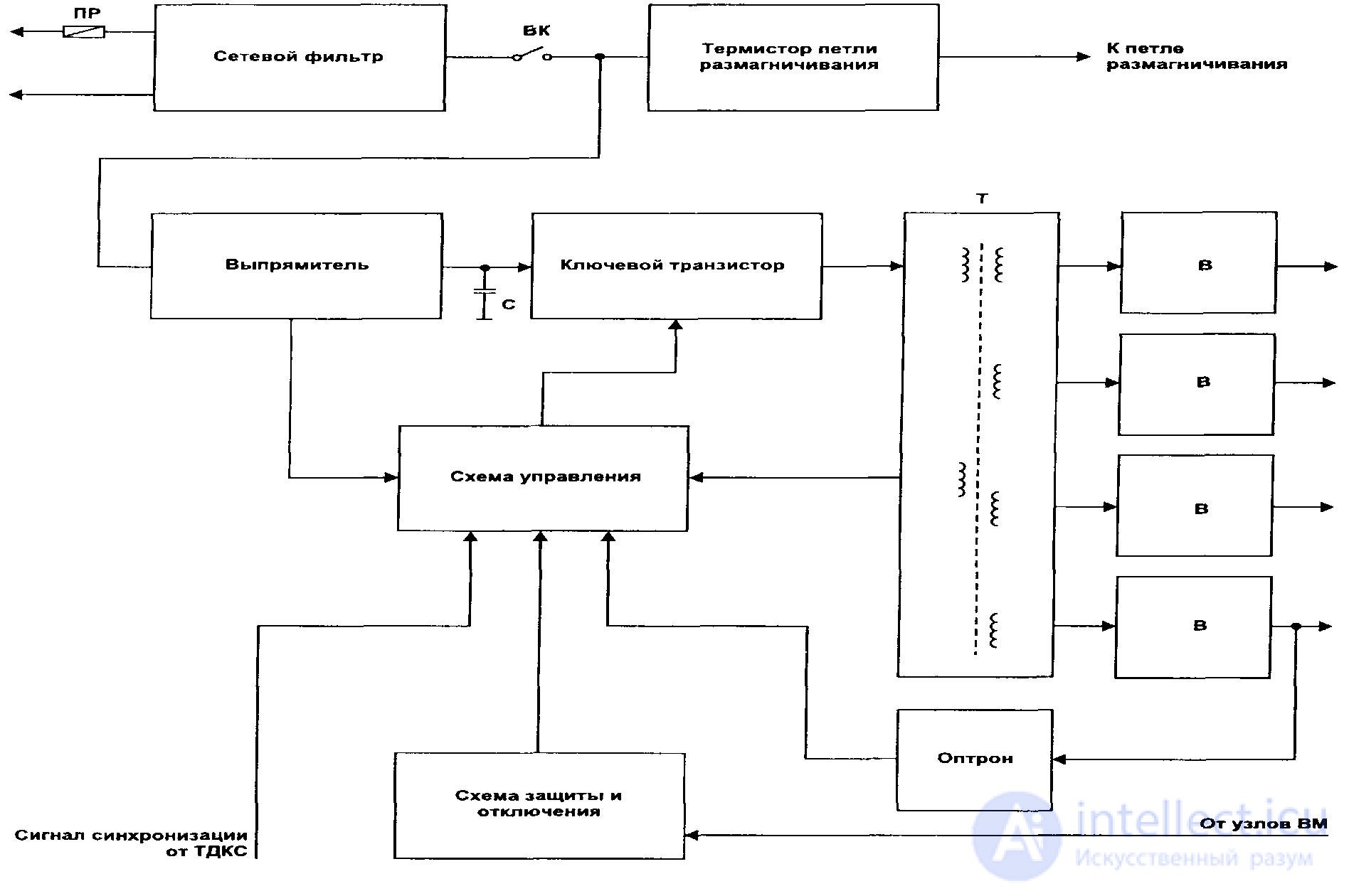
Figure 54 - Typical block diagram of an IP monitor
The output voltage is regulated or stabilized by means of pulse width modulation (PWM) by controlling the duration of the open state of the key transistor. The operating frequency of the IF is 15–80 kHz, it can also be synchronized with the VM line rate to eliminate the formation of “frequency beat” products, which lead to raster distortions and the appearance of ripples or other undesirable effects on the screen.
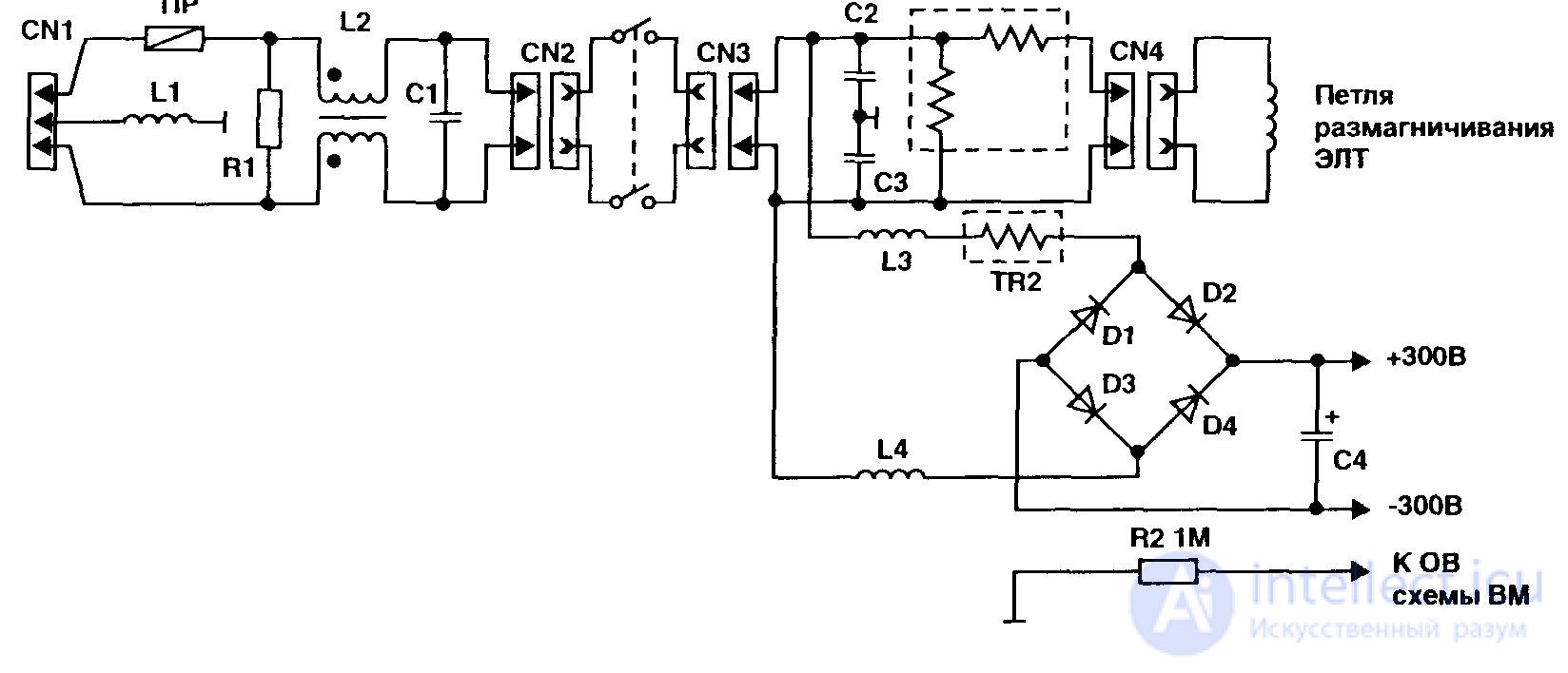
Figure 55 - Input circuit BP
Before starting work, it is necessary to check the power cord and the presence of the supply voltage in the mains.
In a de-energized state, parts are inspected on a VM printed circuit board in the area of the power supply unit node and its basic circuit is determined by the type of applied chips and transistors.
Next, check the fuse at the input of the IP. In the event of a burnout, the following are subject to mandatory verification:
It is useful to check the absence of short circuits at the outputs of the rectifiers in the secondary windings of a power transformer, for which an ohmmeter monitors the resistance on the electrolytic capacitors of the output rectifiers.
If the key transistor and the fuse are intact, then re-enable the VM and the tester successively check the passage of the alternating voltage through the input filter to the rectifier bridge, the DC voltage on the electrolytic capacitor of the rectifier (300 - 350 V) and then on the primary winding of the power transformer. Possible faults may be breaks and cracks on the conductors of the printed circuit board, poor soldering of the conclusions of parts, etc.
In the case of the normal supply of voltage to the collector of the key transistor through the winding of the power transformer, the control signal for the transistor is checked from the control circuit
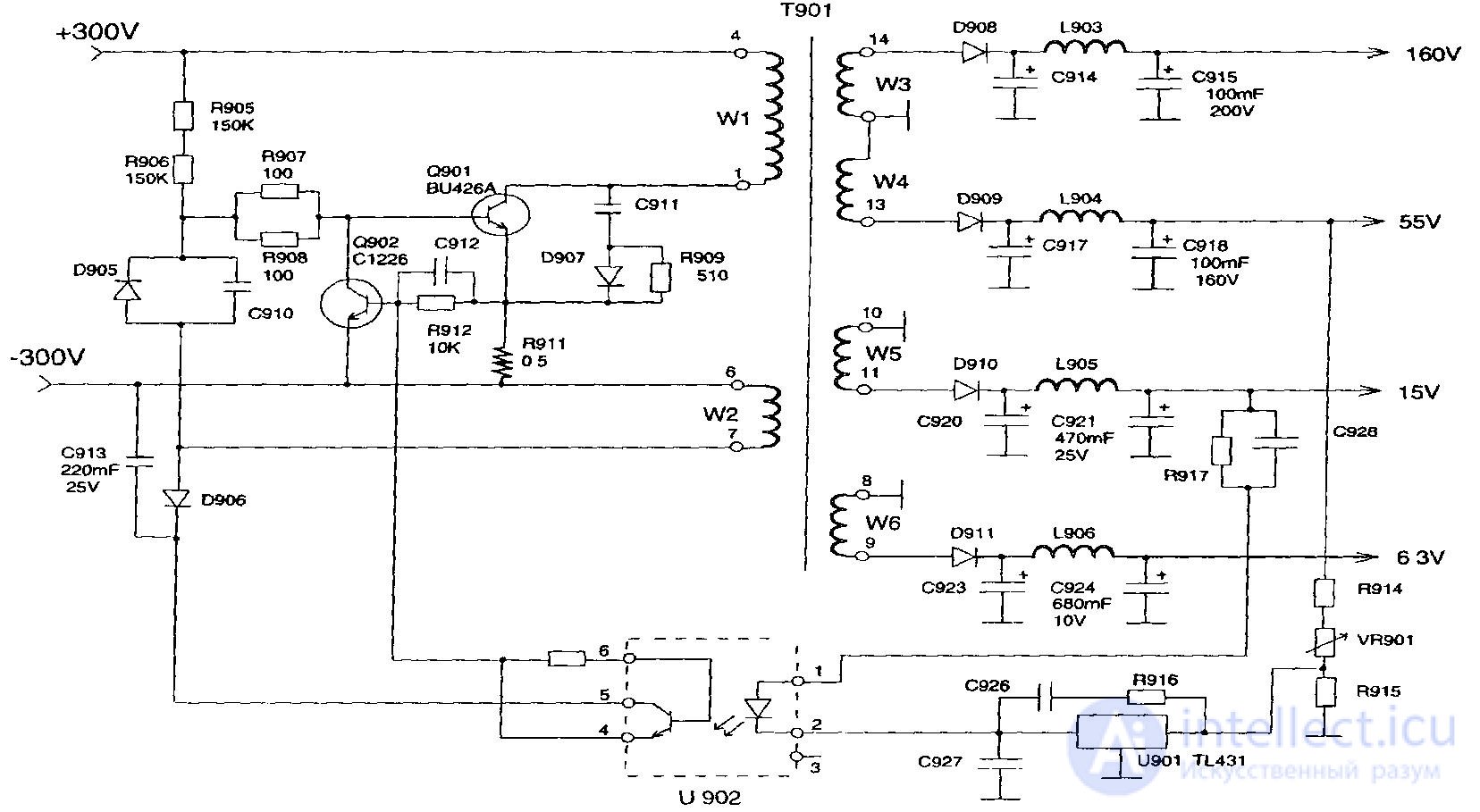
Figure 56 - Option circuit converter PI using transistors
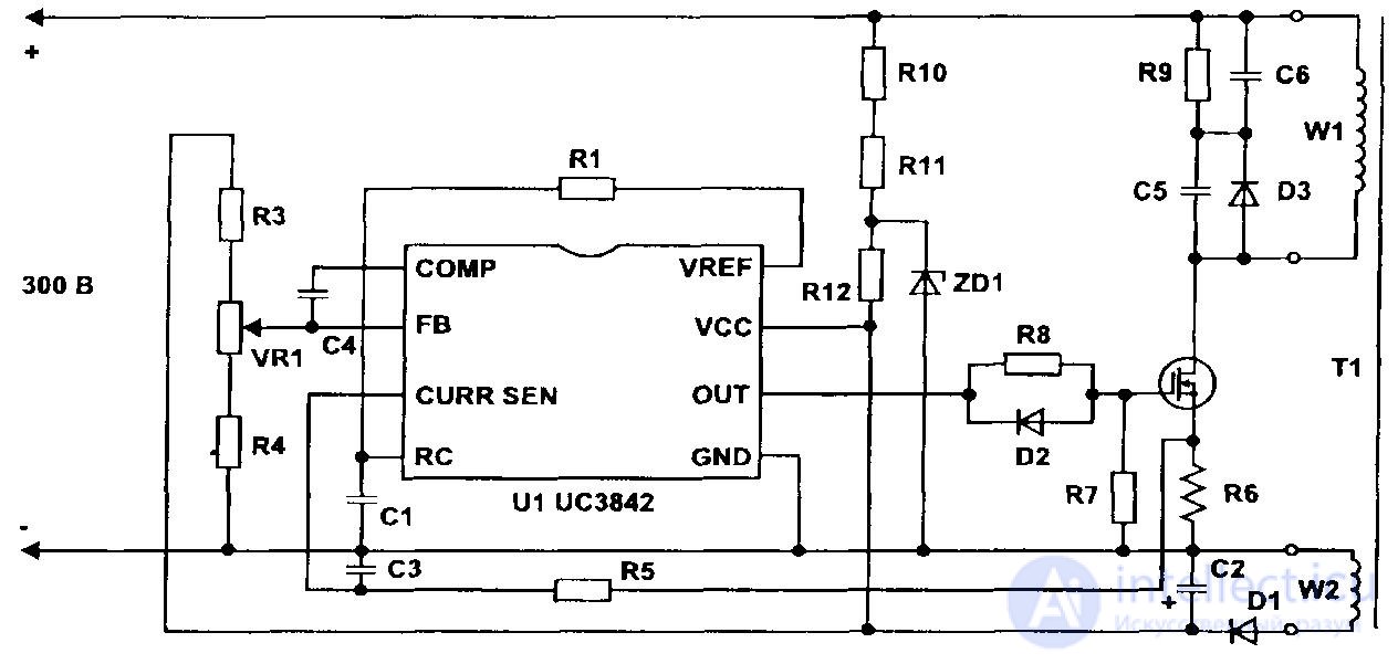
Figure 57 - Variants of the converter PI scheme using MS
At the stage of the final verification, the PIs measure all of its output voltages, if necessary, install them with a trimming resistor and check the voltage ripple on the electrolytic capacitors of the output rectifiers with an oscilloscope. In conclusion of the repair work, it is necessary to check the temperature of the key transistor for one hour to make sure that it does not overheat, and also to check the output voltages again to make sure that the power supply is stable.

Comments
To leave a comment
Diagnostics, maintenance and repair of electronic and radio equipment
Terms: Diagnostics, maintenance and repair of electronic and radio equipment