Lecture
To create a motherboard usually use a special chipset - chipset. Usually it consists of two main parts: the south bridge and the north bridge (North Bridge, South Bridge), but it should be noted that there are now variants made on a single chip. The north bridge is usually used to communicate the processor with memory and AGP, while the south bridge is connected to the north bridge and serves as a peripheral (IDE, ISA, EEPROM, etc.).
The architecture of motherboards is the most true (for today) divided into two groups: using a PCI bus for communication between bridges, and using special interfaces. The use of PCI for communication between bridges is gradually being abandoned, and most new chipsets do not use this interface for communication between themselves. This is primarily due to the low PCI bandwidth: only 133Mb / c. It is obvious that even 2 ATA100 channels will not be able to pump data. I must say that there are many differences between different types of chipsets, but most of them do not affect the overall structure. Below I give the structural diagrams of both options, which are now used.

Figure 33 - Motherboard block diagram
The processor is the main part in the system, as can be seen from the diagram, it is connected to almost all nodes of the board, except for the MIO, and then on many old boards the GATE A20 gate signal was started from the MIO.
VIP1 is the first secondary power supply, all processors starting with the Pentium MMX are dual powered. It should be noted that setting the supply voltage value is automatically supported by relatively new processors, and VID signals can be set with jumpers on the board, and not directly by the processor. Stabilizers are almost always pulsed and special chips are used to implement them. They have a lot of power, and the output stages almost always have additional cooling.
VIP2 - the second secondary power source is used to power all devices not powered from 5V. Despite the fact that the ATX power supply has a 3.3 volt source, many power circuits have additional stabilizers on the board.
In this block diagram, the secondary power sources are not all depicted and are shown very conditionally, in real schemes everything is much more complicated. In any modern board, there are at least 4 secondary power sources: one for memory - 3.3V / 2.5V, the second for AGP 3.3V / 1.5V, the third for logic 3.3V, the fourth for the processor core from 2.0V / 1.45V. The given scheme is valid only for obsolete MBs, for example, I430TX.
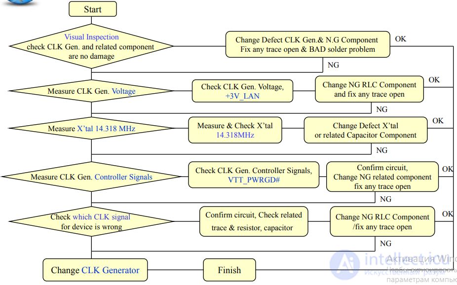
CLOCK is a reference generator, all devices on the motherboard are synchronized with a single reference generator, the synchronization system on the block diagram is represented rather arbitrarily. In general, the computer has the following clock frequencies:
CLOCK BUFFER - the reference oscillator buffer is not used on all boards. In technical boards where the chipset controls memory synchronization, it is used to buffer synchronization signals, for example, it is used in motherboards on the VT82C694X.
MIO –Multi Input Output chip chip input system. In fact, this is a external device, but unfortunately without this device (for example, in case of failure), the motherboard will not be able to turn on.
Includes:
Floppy Drive Controller - floppy drive controller, CMOS - energy-independent memory,
RTC –Real Time Clock real time,
serial and parallel controller (COMA COMB LPT), keyboard controller
system monitoring system of the motherboard. In many chipsets, MIO is integrated partially or completely into the south bridge, for example VT82C686B.
Etc. Ur –– level converter, necessarily used to implement COM.MIO has 5 volt interface, and COM port 12 volt.
BIOS - Basic Input Output System is a basic input / output system, usually implemented as an EEPROM - simply energy-independent memory, the volume usually ranges from 1 Mbit to 4 Mbit (128 Kbytes to 512 Kbytes). It is used to manage the system before loading the operating system. It is the program recorded in the BIOS that the machine performs when the system is turned on. In case of violation of the integrity of the program recorded in the BIOS, the system is not initialized. X-Bus or hshin is a very loud term, just a part of the signals for the BIOS, for example CE (Chip Enable — chip resolution). Started directly from the south bridge.
AGP –Accelerated Graphic Port –accelerated graphic port, bus oriented using high performance video adapters. High transfer rate is provided by pipelining memory accesses. According to the specification, up to 256 requests for memory access can be set in the queue !!!
RAM –Random Access Memory - random access memory, or simply memory.
PCI –Peripheral Component Interconnector – connector for connecting internal peripheral devices. Synchronous bus with a combined bus address, data and commands, allowing to reach data transfer speeds of up to 133 MB / s or in PCI64 up to 266 MB / s.
ISA –Industry Standard Architecture — an industry standard architecture, nowadays an obsolete bus. Most modern chipsets do not support this bus.
USB –Universal Serial Bus – universal serial bus. Now it has become widespread, has great prospects, now there is USB2 standard.
IDE –Integrated Device Electronic – devices with an integrated controller. This bus is used to connect hard drives CD-ROM and DVD-ROM drives.
HI - Hub Interface – an untranslatable play on words (Hub – node or center of something), when new fast peripherals started to appear, PCI didn’t cope with their requests - 2 ATA100 - 200Mb / c - PCI –133Mb / c. At first, this architecture was applied in I82810. In general, the concept of HI applies only to Intel chipsets from other manufacturers, similar interfaces have different names, although they perform the same functions and probably have similar protocols (unfortunately there are no descriptions of these protocols in the generally available documents). VIA has a similar protocol called the V-Link interface.
FWHI - Firm Ware Hub Interface (Node Interface for Firmware - BIOS), after abandoning the ISA interface, there was a problem how to load the BIOS and was easily solved using the above interface. It should be noted that in the VIA chipsets there is no such interface and the BIOS is loaded via the LPC interface.
LPC –Low Pin Count Interface (Interface of a small number of contacts) interface really has only 7 contacts: 4 for data and 3 controllers. Used for connecting MIO for Intel and for BIOS for VIA, SIS.
AC97 is a standard interface for working with an external digital-to-analog or analog-to-digital converter, it is based on its built-in sound cards and cheap modems.
The main and most complex PC board is called the motherboard (mainboard), the general, system board (SP), because it contains the PC's “heart” - a microprocessor. It also contains several very large-scale integrated circuits (VLSI), RAM, ROM, and a number of other microcircuits, switches - jumpers of PC operating modes, expansion connectors for connecting adapter cards and controllers.
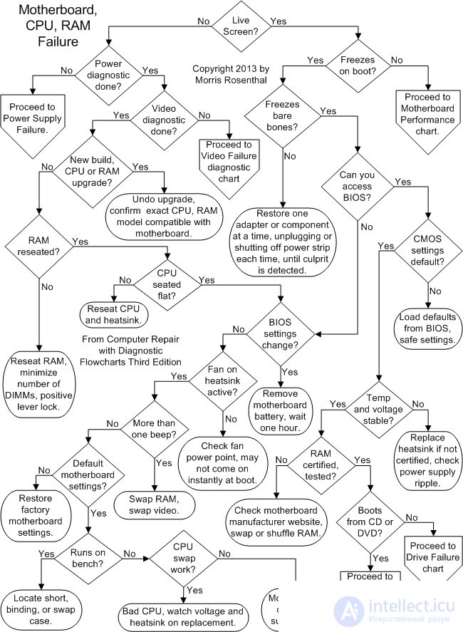
Diagnostics of malfunctions and repair of the joint venture is difficult labor-intensive, but, nevertheless, quite feasible and very interesting business.
SP malfunctions can also be divided into three main types:
The first type includes, for example, contact failure in a multilayer printed circuit board or in one of the expansion terminals of the joint venture.
Contact failure in the PCB is 50% of all faults of the joint venture. (It must be remembered that the installation of power tires is usually done in the inner layers of the board.)
An example of the "faults" of the second kind is the overflow of RAM with resident programs, the connection of a software driver that is incompatible with the connected peripheral device.
software and hardware faults - this is a failure of the ROM BIOS, loss or corruption of configuration information stored in non-volatile RAM (CMOS) at the SP,
Fault diagnosis is carried out in two ways:
The program method is implemented using the built-in program. POST, special diagnostic programs (Checkit, Norton Disk Doctor), as well as using diagnostic boards and MB PACK.
Malfunction of the joint venture can be detected during the initial startup of the PC (self-test, loading of the operating system), during the program run and during operation (20 ... 30 minutes after switching on).
First of all, you should use the visual and audible alarms, which is provided in the PC.
According to the duration, number and alternation of sound signals (Table 1) generated by a computer as a result of self-diagnostics, it is possible to determine its subsystems that contribute to the malfunction. Of course, small POST tests are not able to carry out a full check of the computer’s performance, however this is the first barrier to machine malfunction.
Table 1
Sound signal |
Mistake |
|
1 short |
Failed to update DRAM |
|
2 short |
Parity check failure |
|
3 short |
Crash in the basic area of RAM 64 kb |
|
4 short |
System timer failure |
|
5 short |
CPU failure |
|
6 short |
Keyboard controller error |
|
7 short |
Virtual mode error |
|
8 short |
Memory test failed |
|
9 short |
ROM BIOS checksum failure |
|
10 short |
CMOS error |
|
11 short |
Cache Error |
|
1 long 3 short |
Primary or extended memory failure |
|
1 long 8 short |
did not pass the video test |
If you have a working video card and monitor, the PC, as a rule, additionally displays a digital error code on the screen.
There are hundreds of such codes; for different types of BIOS, they are different, but by the first digit of the code, (as a rule, three-digit), you can determine in which device the failure occurred.
Codes 100 and above mean a malfunction of the motherboard;
200 - RAM errors;
300 - keyboard errors; 400-500 - faults in the display or printer; 600 - UIWM errors;
700 - errors in the mathematical coprocessor;
900 - parallel printer test errors;
1700 - errors in the hard drive circuits.
To facilitate the work in the first step of diagnostics, there is such a wonderful tool as a POST card.
The main function of these diagnostic cards is to fix and display POST codes that are automatically generated by the POST procedure during the process of checking the status of all computer subsystems when the power is turned on or the RESET button is pressed.
The use of a diagnostic board significantly increases the probability of correct fault location. Most of the wired diagnostic boards are written with the expectation that the microprocessor is working properly.
This approach is justified, since the microprocessor fails very rarely. It should be noted that having a listing with BIOS source text in assembler greatly increases the chances of dealing with your problems yourself.
If the BIOS ROM fails, the execution of the POST test program becomes problematic, and errors in the display are not displayed.
To diagnose the second method requires some knowledge in the field of electronics and computer technology and skills to work with test equipment.
The technique of troubleshooting using instruments is to
sequential check:
Fault statistics for ultra large integrated circuits
The most common causes of malfunction of the joint venture are poor-quality wiring board, low level of production technology and poor assembly. If in 1989-1990, mainly buffer chips and peripheral LSIs failed, then the weakest link is now chips from the VLSI set. The pace of development and implementation of new VLSI kits for joint ventures has increased so much that sometimes there are products in production that are characterized by low reliability.
Local overheating of the joint venture has become quite common today, although the build quality is getting better.
продолжение следует...
Часть 1 3.1.4. MAIN MALFUNCTIONS OF THE SYSTEMBOARD, THEIR SIGNS, CAUSES AND ELIMINATION METHODS

Comments
To leave a comment
Diagnostics, maintenance and repair of electronic and radio equipment
Terms: Diagnostics, maintenance and repair of electronic and radio equipment