Lecture
Repair of radio devices is usually performed in the following sequence:
• establish the fact of inoperability;
• the failed block (module) is determined;
• faulty electrical radio elements (ERE) are detected in a failed block (module);
• defective blocks (modules) are restored;
• the device is monitored;
• the device is adjusted;
• verification of the repaired device.
All faults in the RIP can be divided into mechanical and electrical. Mechanical faults occur in the mechanical units. For example, in galetny or push-button switches, in variable and trimming resistors, in mechanisms of adjustment of frequency and many others. Electrical faults occur in electrical circuits and manifest themselves in the form of short circuits, breaks in chips, transistors, capacitors, resistors, inductors, transformers, etc.
Most of the mechanical faults and, in some cases, electrical, are detected during the visual inspection of the equipment. Visual inspection determines the quality of installation, the absence of breaks in the printed tracks and conductors, the quality of the rations (cold rations), and the compliance of the values of the resistors and capacitors of the capacitors (operating voltages) with the requirements of the circuit diagrams is monitored. Often, a visual inspection reveals charred resistors, swollen electrolytic capacitors, the presence of impregnating material leaks in transformers, mechanical damage in ceramic capacitors, etc.
The presence of electrical faults in the equipment may be indicated by smells from overheated windings of transformers, chokes, resistors, changes in the tone of sound vibrations caused by the operation of transformers (rumble with a frequency of 50 Hz). When conducting a visual inspection, it is necessary to manually check the mounting quality of mechanical components (transformers, chokes, switches, electrical capacitors, variable and semi-variable resistors, etc.).
After the repair of the AIS is carried out, it is monitored for its performance, which consists in checking several technical parameters of the device. For example, in an oscilloscope, whether the brightness of the beam is regulated, whether the beam moves down, up, whether the beam is swept when a sinusoidal signal is applied to the Y input, etc.
After the performance monitoring of the RIP is carried out its adjustment. The adjustment and adjustment works are aimed at bringing the technical parameters of the RIP in accordance with the requirements of regulatory and technical documentation (NTD) and consist in the fact that, without changing the electrical circuit of the device and its design, by selecting the circuit elements or adjusting the ERE achieve the optimal values of output parameters. At the beginning, the individual blocks (modules) are adjusted, and then the whole RIP is adjusted in complex.
Due to the fact that in most cases RIs are used to measure technical parameters (TP) and characteristics of electronic equipment (REA), after carrying out its repair, performance monitoring and adjusting the RIP, it is imperative to undergo metrological calibration in order to establish compliance with its main TP and characteristics of the requirements of regulatory and technical documentation. Such documentation includes: GOSTs, OSTs, TU, technical operating instructions, technical passports, etc.
When searching for faults in radio measuring devices, auxiliary devices are widely used: oscilloscopes, voltmeters, multimeters, logic probes, logic signal generators, current tracers, and others.
With the help of an oscilloscope, the parameters of constant (with open input) and variable voltages, durations of fronts and decays of pulses, frequency and oscillation periods are measured. Oscilloscopes allow viewing parameters of modulated radio frequency signals on a cathode-ray tube (CRT) screen, estimating the modulation factor and the degree of distortion of the modulated signal. In addition, the oscilloscope allows you to take amplitude-frequency (AFC) and phase-frequency (PFC) characteristics and carry out other complex measurements in a wide frequency range. Digital oscilloscopes that have appeared in recent years have opened up new research opportunities by memorizing an electrical signal and its subsequent processing, separating signals from interference, and also reproducing received and transformed signals on a printing device, etc. When working with an oscilloscope, you should know and remember that it measures the instantaneous value of the amplitude of the alternating voltage U p and current, unlike voltmeters and digital multimeters, which measure the effective value of the voltage U and current. The mathematical connection of these quantities is described by the following formulas:

where U m is the amplitude value of the voltage.
Example 1. The oscilloscope measured the range of an alternating voltage U = 28.2 V. Determine what voltage value the voltmeter or digital multimeter will show.

Example 2. What is the magnitude of the magnitude of the alternating voltage will show the oscilloscope, if using it to measure the voltage in the industrial network?
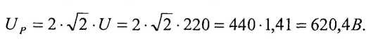
The last example shows why it is imperative to use a voltage divider when measuring the voltage of an industrial network. Otherwise, you can disable the device, because most oscilloscopes can measure the highest voltage in the range of 80-160 V.

Comments
To leave a comment
Diagnostics, maintenance and repair of electronic and radio equipment
Terms: Diagnostics, maintenance and repair of electronic and radio equipment