Lecture
Electron Beam (CRT) is used for visual display
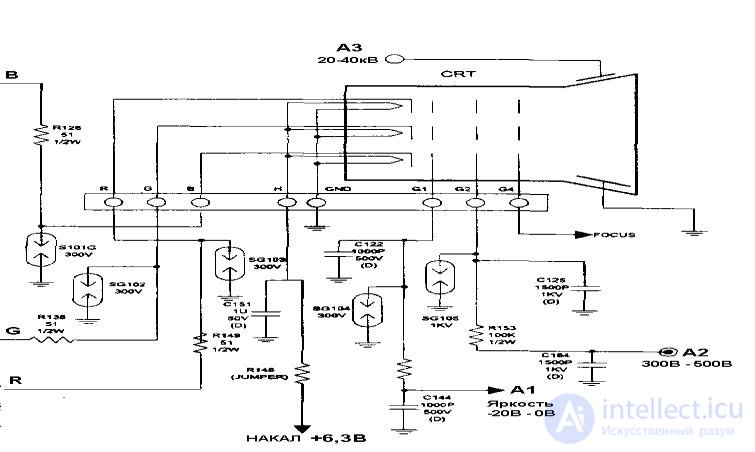
N output | Destination output | Voltage | |||
one | Focusing voltage | 4-6kV | |||
A2 | |||||
2 | Missing | ||||
3.4 | Not connected | ||||
five | Modulator | -10 - + 10V | |||
6 | Cathode G (green gun) | 90V | |||
7 | Accelerating voltage A1 | 390V | |||
eight | Cathode R (Red Cannon) | 90V | |||
9 | Glow 1 | 6.3B | |||
ten | Glow 2 | ||||
eleven | Cathode B (blue gun) | 90V | |||
12 | Not used |
Accelerating voltage is applied to a separate anode contact on a CRT cylinder with a special high-voltage wire. Its excessive magnitude leads to an increase in X-ray radiation when electrons strike the mask, and an underestimated magnitude worsens the focusing conditions of the beam, therefore, it must be fairly accurately established. For color CRTs with a screen size of 14 ", the voltage should not exceed 25 kV (usually set to about 24.5 kV), in large-sized color CRTs (19-20") it can reach 27-40 kV, its exact value is taken from the service instructions.
In a CRT with a flat screen (with a size larger than 15 "), the so-called dynamic focusing is used, since the time of flight of electrons from the gun to the edges of the screen and its middle is different and it is necessary to adjust the focusing conditions in order to maintain the minimum spot size on the horizontal line scan. dynamic focus controls typically refer to a line scan node.
Diagnosis (requires special attention to the implementation of the rules of TB !!)
Diagnostics of the connection scheme of a CRT is carried out by successively performing the following checks:
A sign of good performance of the power supply circuits of a CRT is the presence of a glow on the monitor screen and the ability to adjust the brightness and focus of the tube.

Comments
To leave a comment
Diagnostics, maintenance and repair of electronic and radio equipment
Terms: Diagnostics, maintenance and repair of electronic and radio equipment