Lecture
System resources are communication channels, addresses, and signals used by computer nodes to communicate using buses. Usually, system resources mean:
All these resources are needed for various computer components. Adapter boards use resources to interact with the entire system and to perform their specific functions.
Each adapter card needs its own set of resources. For example, serial ports require IRQ channels and unique I / O port addresses to work, and at least one more DMA channel is required for audio devices. Most network cards use a 16-KB memory block, an IRQ channel, and an I / O port address.
As additional boards are installed in a computer, the probability of conflicts related to the use of resources increases significantly.
A conflict occurs when installing two or more cards, each of which requires an IRQ line or an I / O port address. To prevent conflicts, most of the boards have jumpers or switches that can be used to change the I / O port address, IRQ number, etc.
Memory addresses
Some devices need a buffer for temporary storage of the data they use. You must ensure that these areas do not overlap for different devices.
Interruptions
Interrupt request channels (IRQ), or hardware interrupts, are used by various devices to inform the system board (processor) that a particular request must be processed.
The interrupt channels are the conductors on the motherboard and the corresponding pins in the connectors. Conventionally, the interrupt handling scheme is as follows:
The pointers in the vector table determine the memory addresses for which the driver software for servicing the card that sent the request is written. Since interrupt sharing is usually not allowed on the ISA bus, installing new cards may show a shortage of interrupt lines. If two boards use the same IRQ line, then their normal operation will break the resulting conflict.
PCI bus interrupts
The local PCI bus was designed with interrupt sharing. Each PCI device should work correctly on the same interrupt line with other PCI devices. This is done as follows: the fact of the presence of a signal on the interrupt line is not determined by the front, i.e. change in voltage level, and on the very fact of a certain voltage. Several devices can change the voltage in a line at once, becoming, as it were, in a queue for maintenance.
The IBM PC AT computer had only one bus over which devices could communicate with the processor and memory - ISA. Most of the interrupt lines were assigned to standard ISA-devices, the rest were reserved for the future. When this future came, it turned out that the new universal PCI bus had only four free interrupts. Therefore, a clever interrupt sharing mechanism (IRQ Sharing) and dynamic number redefinition (IRQ Steering or Mapping) was invented, and the ACPI system was introduced to distribute interrupts.
ACPI (Advanced Configuration and Power Interface) was developed in 1997 by three companies Microsoft, Intel and Toshiba. The ACPI system manages the computer’s energy-saving functions, such as automatically turning off the power supply after a successful shutdown of the operating system. The second function of ACPI is the automatic allocation of system resources within a computer. While ACPI is in action, you cannot change any parameters related to interrupts. Moreover, the ACPI system supports the operation of the extended interrupt controller APIC.
APIC (Advanced Programmable Interrupt Controller) - advanced programmable interrupt controller. For multiprocessor systems, this is a necessary system, since it allows distributing the load on the work with devices between processors. That is, this controller can be programmed to process some interrupt lines with the first processor, and some with the second.
IRQ Sharing - the system allows two devices at the same time be on one interrupt. Physically, it turns out that several devices can hang on the same IRQ line, while the management between them is provided by the operating system. IRQ Sharing is an ambiguous system, since its use is necessary for normal PC operation, but a variety of problems and glitches are possible.
The combination of the above systems was recognized as a standard and included in the list of computer hardware requirements - PC2001.
The essence of the PCI device interrupt control mechanism is as follows. In general, there are four physical PCI interrupt lines called PIRQ0, PIRQ1, PIRQ2 and PIRQ3. They are connected to the interrupt controller. Each PCI device, for its part, has four slots, called INT A, INT B, INT C, and INT D. It is possible to connect lines to the slots in any order. For example, for the first PCI slot, you can do this: PIRQ0 - INT A, PIRQ1 - INT B, PIRQ2 - INT C, PIRQ3 - INT D. And for the second, it is different: PIRQ0 - INT B, PIRQ1 - INT C, PIRQ2 - INT D, PIRQ3 - INT A. Typically, a device requires only one interrupt line connected to INT A. When installed in the first slot, the device uses the PIRQ0 line and the second slot on the same pin will have the PIRQ1 line. Thus, devices in different slots will use different physical interrupt lines. A hardware conflict between them will be excluded.
The AGP bus, being essentially a specialized PCI modification, also uses one of the PIRQ lines - usually PIRQ0.
PIRQ lines are connected to the interrupt controller. They, like other lines, are assigned logical IRQ numbers. If there are several devices on the same physical line (and this is valid), then all of them will have the same IRQ number. If the devices are on different physical lines, they can still get the same IRQ numbers. Normal drivers will allow them to work freely without loss of performance, since the PCI bus can still be captured by only one device. The main thing is to recognize which device the signal came from.
For modern systems, the four lines are not enough, so the new chipsets often use eight PIRQ lines, which in the same way are connected in different combinations to PCI slots and devices built into the board.
PIRQ line numbers are assigned automatically thanks to the Plug & Play mechanism. But there are ISA-devices that support Plug & Play. They also have the ability to automatically get an IRQ number. But their interrupt line belongs to them exclusively, and if one of the PIRQ lines gets the same number, an insoluble conflict will arise.
So, we found out that PCI devices should be free from problems with IRQ conflicts. If they, of course, work correctly, but this is not always the case. In addition, drivers must support an interrupt sharing mechanism. ISA devices do not know how to share interrupt lines and therefore are provocateurs of conflicts. Consequently, the task of resolving conflicts is reduced to the correct allocation of numbers (the source of problems is ISA devices and “curves” drivers) or to dilution along different physical lines (“curves” PCI controllers).
Most new systems allow the use of a single interrupt by multiple PCI devices. All system BIOSs that meet the Plug and Play specifications, as well as operating systems starting with Windows 95b (OSR 2), support interrupt control. In such computers, the entire system takes care of interrupts.
Direct Memory Access Channels
Direct memory access (DMA) channels are used by high-speed data exchange devices.
A single DMA channel can be used by different devices, but not simultaneously. For example, DMA channel 1 can be used both as a network adapter and as a tape drive, but you will not be able to write information to a tape while working on the network. To do this, each adapter needs to allocate its own DMA channel.
DMA channels of 8-bit ISA bus. Four DMA channels can be used on this bus for high-speed data transfer between I / O devices and memory.
Of all the DMA channels, only the DMA 2 channel used by the floppy controller has a standard assignment in all computer systems.
DMA 4 channel is not used and is not represented in bus slots.
DMA 1 and DMA 5 channels are commonly used in sound cards, for example, in Sound Blaster 16. For high-speed information transfer, this card uses both 8- and 16-bit channel.
I / O port addresses
Through the input-output ports to the computer, you can connect a variety of devices to expand its capabilities. A printer connected to one of the parallel LPT ports allows you to print out the results of your work. A modem connected to one of the COM serial ports provides telephone communication with other computers located thousands of kilometers from you. A scanner connected to an LPT port or a SCSI adapter allows you to enter graphic images or text directly from a sheet of paper into a computer and convert them to the required format for further processing.
Most computers have at least two serial ports and one parallel. Serial ports are designated as COM1 and COM2, and parallel ports - LPT1. In principle, up to four serial (COM 1 – COM4) and three parallel (LPT1 – LPT3) ports can be installed in a computer.
I / O ports allow communication between devices and software on a computer. They are similar to two-way radio channels, since the exchange of information in this and the other direction takes place on the same channel.
The computer has 65,535 ports, numbered from 0000h to FFFFh. Although many devices use up to eight ports, their number
The property is more than sufficient. The biggest problem is that two devices do not accidentally assign the same port.
The most modern systems with automatic self-tuning (Plug and Play) automatically resolve any conflicts due to ports, choosing alternative ports for one of the conflicting devices.
Special programs - drivers - interact primarily with devices using various port addresses. The driver must know which ports the device uses to work with it. This is usually not a problem, since both the driver and the device are usually supplied by the same company.
The motherboard and chipset of the system logic usually use the addresses of input / output ports from 0h to FFh, and all other devices from 100h to FFFFh.
Computer resources are limited, and the needs for them are truly unlimited. By installing new adapter cards in your PC, you significantly increase the likelihood of conflicts between them. If the computer's bus does not prevent them automatically, then this has to be done manually. What are the signs of conflicts related to the misuse of resources? One of them is the situation when a device stops working. But there may be other signs, for example:
Device Manager in Windows versions marks conflicting devices with a yellow or red icon. This is the fastest way to detect conflicts.
All PC resources are distributed twice - first by means of BIOS and then by means of Windows, respectively, and the allocation of system resources is possible at two levels (BIOS -Windows).
In the system, IRQ numbers are distributed between physical lines twice. The first time this makes the system BIOS when the system boots.
Each Plug & Play device (all PCI, modern ISA, integrated devices), or rather its interrupt line, is assigned one number out of ten possible. If there are not enough numbers, several lines get one common. If these are the PIRQ lines, then that's okay - if there are normal drivers and support from the operating system (see below), everything will work. And if one ISA-device or a PCI-and ISA-device receive one number, then the conflict is simply inevitable, and then you need to intervene in the distribution process.
First of all, you need to disable all unused ISA-devices (they are also present in systems without ISA slots) —COM1, COM2 ports and a disk drive. You can also disable the EPT and ECP modes of the LPT port, then the IRQ7 interrupt will become available. In BIOS Setup we need the section "PCI / PNP Configuration". There are two basic ways to influence the distribution of IRQ numbers: block a specific number and directly assign a PIRQ line number.
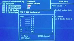
With the option section "PCI / PNP Configuration, you can achieve the correct prioritization of interrupt lines to devices:
That is, you can change interrupts for slots and devices attached to them with your hands. If all options are set to Auto, then the automaton deals with the distribution of interruptions with an algorithm that is very similar to the ACPI system algorithm. Sometimes the indication of interruptions is not numbers, but letters - A, B, C, D. Just as with numbers, letter interrupts allow you to control yourself, with the highest priority being at letter A.
It is important - If you change the priority distribution of the interrupt lines of an installed operating system with the ACPI core, the operating system will no longer boot, before correcting this value back to APIC. If you set the option in the PIC before installing the operating system, the ACPI core will not use virtual interrupts, but will listen to the BIOS instructions while maintaining energy-saving functions.
Using the functions of the BIOS should also disable unused devices:
If the above devices are not used, setting Disabled will disable them and free up the resources they use.
Distribution of IRQ numbers using Windows
The second time interrupt numbers are distributed by the operating system. Windows begins to interfere with the actions taken by the BIOS only in extreme cases. If there is a normal BIOS, the techniques described here will not be needed. On the user side, there are two ways to allocate PC resources.
The first way is this is the full use of systems ACPI and IRQ Sharing If the ACPI systems, and accordingly the APIC, are turned on, then the operating system assumes that it has 256 interrupts, while there were 16 real interrupts and so on. The remaining 240 interrupts are virtual interrupts that are clones of real ones. ACPI automatically distributes interrupts and does not allow the user to change them. If the device agrees to work in cooperation with another device, then there is every chance that ACPI will put them on the same physical line. If you do not control this situation, then practically all devices installed in the computer can appear on one physical interrupt, even if there are free interrupts. This will lead to severe braking of the entire system and serious malfunctions.
Decision:
The advantage of this approach is that there is no need for user intervention. That is, do nothing. Simply plug in the video card, processor, memory, and so on into the motherboard, and then install an operating system that normally supports ACPI. And this is Windows XP or Windows 2000. That's it. The computer will work. It is in this form that almost all computers assembled in Russia are sold. Подход прост: если работает и тормозит – то это не гарантийный случай, а проблема пользователя.
Второй способ заключается в отказе от использования ACPI and APIC, но спараллельным использованием IRQ Sharing. Отказ от систем ACPI и APIC означает , что операционная система знает о наличии у неѐ только 16 прерываний, а не 256, но система IRQ Sharing позволяет находиться на одном прерывании нескольким устройствам. При этом отслеживать картину прерываний уже можно, и выбирать соседей по своему усмотрению - тоже.
Решение: Для начала нужно отключить все порты, которые не используются. Не пользуетесь LPT – отключить. Не пользуетесь вторым COM-портом и дополнительными USB-каналами – та же судьба, отключить. Каждое устройство должно иметь отдельное прерывание и ни с кем не пересекаться. Это вопрос приоритетов и потребностей, потому что при использовании данного способа половина компьютера оказывается отключенной, зато всѐ остальное работает как часы. Самым первым изменением, с которого мы начнем настройку системы, будет замена ядра операционной системы для отключения функций ACPI. Как уже упоминалось ранее, после этого компьютер потеряет все энергосберегающие функции и перестанет сам выключаться после завершения работы операционной системы. Для этого нужно зайти в контрольную панель, выбрать иконку «Система», затем перейти в закладку «Оборудование» и нажать на «Диспетчер устройств». Затем открыть раздел «Компьютер» и двойным кликом нажать на «Компьютер с ACPI». Выбрать закладку «Драйвер» и нажать на кнопку «Обновить».

Select "install from a specified location", and then abandon the automatic driver search and choose to install the driver manually. In the window that appears, uncheck "only compatible devices" and select the driver "Standard computer".
После нажатия на кнопку «Далее» компьютер скопирует необходимые файлы и уйдет на перезагрузку. После перезагрузки компьютер начнет находить ВСЕ устройства заново, включая системные устройства, но будет находить драйверы для них в автоматическом режиме. Некоторые устройства не проходят автоматическую установку, но для них достаточно выбрать автоматический поиск драйверов. После этого компьютер еще раз перезагрузится и после этого заработает в нормальном режиме. Всё, система ACPI отключена. Для того, чтобы снова включить ACPI, нужно повторить все вышеописанные действия, только выбрать «Компьютер с поддержкой ACPI».
Затем следуем открыв закладку свойств конфликтующих устройств выполнить распределение ресурсов вручную.
Системы Plug and Play
Системы Plug and Play (P&P). Впервые они появились на рынке в 1995 году, и в большинстве новых систем используются преимущества этой технологии. Раньше каждый раз при добавлении нового устройства пользователи ПК должны были пробираться сквозь "дебри" переключателей и перемычек, а результатом чаще всего были конфликты системных ресурсов и неработающие платы.
Сейчас спецификации Plug and Play применяются в стандартах ISA, PCI, SCSI, IDE и PCMCIA.
Чтобы реализовать возможности Plug and Play, необходимо следующее:
Каждый из этих компонентов должен поддерживать стандарт Plug and Play, т.е. удовлетворять определенным требованиям.
Аппаратные средства. Под аппаратными средствами подразумеваются как компьютеры, так и платы адаптеров. Не надо думать, что в компьютере Plug and Play нельзя использовать старые адаптеры шины ISA. Применять их можно, но, разумеется, преимуществ, которые предоставляет автоматическая конфигурация, уже не будет.
Возможности Plug and Play в BIOS реализуются в процессе выполнения расширенной процедуры POST при включении компьютера. BIOS идентифицирует и определяет расположение плат в слотах, а также настраивает адаптеры Plug and Play. Эти действия выполняются в несколько этапов.
Операционная система. В ПК можно установить как новую версию Windows, так и расширения к имеющейся операционной системе. Операционная система должна сообщить вам о конфликтах, которые не были устранены BIOS. В зависимости от возможностей операционной системы вы можете настроить пара-метры адаптеров вручную (с экрана) или выключить компьютер и изменить положение перемычек и переключателей на самих платах. При перезагрузке будет выполнена повторная проверка и выданы сообщения об оставшихся (или новых) конфликтах. После нескольких "заходов" все конфликты, как правило, устраняются.

Comments
To leave a comment
Diagnostics, maintenance and repair of electronic and radio equipment
Terms: Diagnostics, maintenance and repair of electronic and radio equipment