Lecture
Gcd device
Typical NOD drive consists of
On the electronics board , all drive control circuits, an interface with a computer controller (IDE, SATA), interface connectors and audio output are located.
A spindle motor serves to drive a disk at a constant or variable linear speed.
A stand is attached to the axis of the spindle motor , to which the disc is pressed after loading. The disk is pressed against the stand using a washer located on the other side of the disk. The stand and washer contain permanent magnets, the force of attraction of which presses the washer through the disk to the stand.
The optical system consists of a carriage, where the laser emitter, the focusing system and the photodetector, and the mechanism of its movement are located. The focusing system is a movable lens driven by an electromagnetic system. A change in the magnetic field strength causes the lens to move in a vertical plane and re-focus the laser beam.
The system for moving the head has its own miniature engine driving the carriage with the help of a worm (sometimes gear) transmission.
Principle of operation of GCD
A semiconductor laser generates a low-power infrared beam that hits a reflective mirror. A servo motor, following commands from a built-in microprocessor, shifts the movable carriage with a reflecting mirror to the desired track on the CD. The beam reflected from the disk is focused by a lens located under the disk, is reflected from the mirror and hits the separation prism. The separation prism directs the reflected beam to another focusing lens. This lens directs the reflected beam in the photo sensor, which converts light energy into electrical impulses. The signals from the photo sensor are decoded by the embedded microprocessor and transmitted to the computer as data.
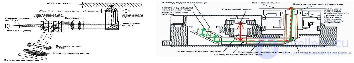
Figure 47 - Block diagram of the optical head Figure 48 - Optical head
Mechanical faults make up 80 ... 85% total number of faults. They can be divided into several main groups:
The lack of lubrication leads to the fact that the CD-ROM hardly pushes the carriage with the disk. In simple mechanisms, where each element performs several functions, the lack of lubrication leads, for example, to jamming the carriage lock and eliminates the possibility of using a CD-ROM.
The accumulation of dust and dirt on the moving parts, especially at the edges of the slide of the carriage, makes it almost impossible to lock the mechanism, and as a result, the CD-ROM constantly ejects the disc.
Filling of the friction surfaces leads either to stopping the carriage mechanism in intermediate positions, or to disk slippage during rotation. Both make the use of CD-ROM impossible. The result of a violation of the adjustments of the transport mechanism also leads to a similar result.
The lack of lubrication mechanism leads to the fact that the drive hardly pushes the disk drive with the disk. It is advisable to periodically lubricate lithol CD-ROM drive transport mechanism.
Malfunctions of the optical-electronic information reading system .
Despite its small size, this system is a very complex and precise optical device. According to the frequency of occurrence during the first one and a half to two years of operation, failures of the optical system amount to 10 ... 15% of the total number of faults.
The main parts of the system are (see Figure 48):

Figure 49 - The structure of the links of the optical-electronic information reading system
Disk spin control servo ensures consistency linear speed of the track reading on the disk relative to the laser spot.
Characteristic signs of a malfunction are either lack of rotation of the disc, or, conversely, acceleration to the maximum speed of rotation. When you try to remove a disk using the controls, the carriage opens with a rotating disk.
Characteristic features of good performance are clearly following phases:
The servo-system for positioning the information reading head ensures a smooth lead of the head to the specified recording track with an error not exceeding half the width of the track in the search modes for the required piece of information and normal playback.
The movement of the read head, and with it the laser beam, across the disk field is carried out by the head motor. The engine is controlled by forward and reverse movement signals from the control processor, as well as signals generated by the radial error processor.
Characteristic signs of failure are:
Radial tracking servo system holds the laser beam on the track and the optimal conditions for reading information.
The system is based on the three light spot method. The essence of the method consists in dividing the main laser beam with the help of a diffraction grating into three separate beams having a slight divergence.
The performance of the radial tracking system can be monitored by changing the error signal sent to the tracking drive.
Servo autofocus provides precise focusing laser beam in the process of working on the working surface of the disk.
The efficiency of the focusing system can be judged by the characteristic movements of the focal lens at the time of the disc start, and by the start signal of the acceleration mode of the disc when the focus of the laser beam is found.
The information reading system contains a photo-detector array and differential signal amplifiers.
The normal operation of this system can be judged by the presence of high-frequency signals at its output as the disk rotates.
The control system of the laser diode provides the nominal current excitation of the diode in the mode of starting the disk and reading information.
A sign of normal system operation is the presence of an RF signal with an amplitude of about 1 V at the output of the reading system.
All faults of the GCD electronic filling belong to the third group of faults. Despite the relatively small (relative to the total number of NOD defects) percentage of cases of failure of electronics - 5 ... 10%, troubleshooting of electronic circuits is the most time-consuming part of the repair.
Typical malfunctions of GCD and methods of their elimination
The following typical malfunctions of GCD components can be distinguished:
• The computer does not identify the drive.
• CD loading / unloading does not work.
• Do not pass GCD tests
The computer does not identify the gcd device , LED is off access to the drive. First check the installation of the "Slave" jumper on the drive connector.
Then control the health of the interface cable EIDE and the correctness of its connection to the system board of the computer.
Finally, verify that the installation of the CD-ROM device in the BIOS - Setup. If the drive still does not work after these checks, check the interface connector signals using an oscilloscope.
CD loading / unloading does not work
The receiver does not slide out when you press the "Open" key and does not slide in when you press the "Close" key
First, they check for the arrival of a +5 V voltage on the IC601 (system drive control processor) by pressing the "Open" key. In the presence of this voltage, check the presence of control signals DZVD on the motor winding.
In the presence of control signals, the condition of the motor itself is checked: an external DC power supply (9 V) is connected to the motor contacts. If the motor shaft begins to rotate rapidly, we can assume that the motor is healthy. If the motor does not rotate, rotates too slowly, or heats up quickly, use an ohmmeter to check the resistance of its windings: Ro6m = 6.5 Ohm. In the case of a significant (more than 30%) deviation of Ro6m from the specified value, replace the engine itself.
Next, check the serviceability of the mechanism of movement of the disc receiver, consisting of a worm gear, plastic gear rack and the disc receiver itself.
Mechanical failure of parts of the transport mechanism is quite common.
The receiver does not open or close completely.
First, check the serviceability of the transport mechanism, if necessary, cleaned of dust and dirt and grease lithologic or any viscous lubricant. Then they check the triggering of the contact group ("triples") when opening and closing the disc receiver (Figure 49). If necessary, this contact group is regulated.

Figure 50 - General view of the contacts of the control of the operation of the disc receiver
Disk receiver spontaneously extends when power is applied to the drive
There is no locking of the disk receiver due to the fuzzy actuation of the contact group ("triples"). If necessary, this contact group is regulated.
Cannot read information from a CD or read out is faulty.
The main causes of these problems may be the following:
The intensity of the laser beam is insufficient Symptom:
Drive after half a year of work (as a rule, immediately after the expiration of the warranty) stops reading CDs or DVDs. Usually the problem manifests itself gradually.
First, the rewritable discs of one of the formats start to read poorly, then there comes the turn of the poor reading of disposable CD-R or DVD-R discs and finally comes the turn of pre-fabricated pressed discs.
Repairs:
The problem is usually not related to contamination of the optical drive system. A dirty lens and a translucent mirror beneath it equally degrade the reading quality of both types of media. Two laser modules are installed in the reading head of universal combo drives. One of them is used to read and write DVD discs, the other for CDs. Over time, a decrease in the brightness of one of the lasers may occur.
Small trimming resistors mounted directly on the head regulate the current through the laser diode and, by changing their rating, it is possible to change the brightness of the laser radiation within certain limits. In the figure they are circled and marked with numbers 1 and 2.

Figure 51 - General view of the optical head. 1 and 2 laser diode current adjustment resistors
A generalized GFD troubleshooting algorithm is presented in Figure 52.
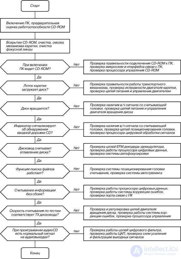
Figure 52 - Generalized GCD troubleshooting algorithm

Comments
To leave a comment
Diagnostics, maintenance and repair of electronic and radio equipment
Terms: Diagnostics, maintenance and repair of electronic and radio equipment