Lecture
Surprising is the complete lack of information about such common devices as uninterruptible power supplies. We break through the information blockade and proceed to publish materials on their device and repair. From the article you will get a general idea of the existing types of uninterruptible power supplies and a more detailed, at the level of the circuit diagram, about the most common Smart-UPS models.
The reliability of computers is largely determined by the quality of the electrical network. The consequences of power outages such as surges, ups, downs and voltage loss can be key locks, data loss, damage to the system board, etc. Uninterruptible power supplies (UPS) are used to protect expensive computers from network troubles. The UPS allows you to get rid of the problems associated with poor quality of power supply or its temporary absence, but is not a long-term alternative source of power supply, like a generator.
According to the expert and analytical center “SK PRESS”, in 2000 the sales volume of UPSs in the Russian market amounted to 582 thousand units. If we compare these estimates with data on sales of computers (1.78 million units), it turns out that in 2000 every third computer purchased is equipped with an individual UPS.
The vast majority of the Russian UPS market is occupied by products of six companies: APC, Chloride, Invensys, IMV, Liebert, Powercom. APC products have been maintaining a leading position in the Russian UPS market for many years.
UPSs are divided into three main classes: Off-line (or stand-by), Line-interactive and On-line. These devices have various designs and characteristics.
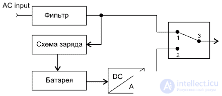
Fig. 1. Block diagram of the UPS class Off-line
The block diagram of the Off-line UPS is shown in Fig. 1. During normal operation, the load is powered by the filtered mains voltage. To suppress electromagnetic and radio frequency interference in the input circuits, EMI / RFI Noise filters on metal oxide varistors are used. If the input voltage becomes lower or higher than the set value or disappears altogether, then the inverter is turned on, which in normal mode is in the off state. By converting the constant voltage of the batteries to alternating, the inverter supplies the load from the batteries. The shape of its output voltage is rectangular pulses of positive and negative polarity with an amplitude of 300 V and a frequency of 50 Hz. Off-line class UPSs operate uneconomically in power networks with frequent and significant voltage deviations from the nominal value,since frequent switching to battery operation reduces the battery life. The power of Back-UPS models produced by ARS is in the range 250 ... 1250 VA, and the models Back-UPS Pro in the range 2S0 ... 1400 VA.
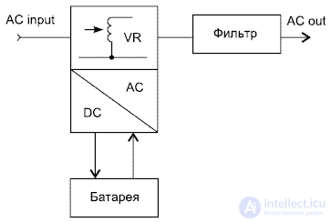
Fig. 2. Block diagram of Line-interactive class UPS
The block diagram of the Line-interactive class UPS is shown in Fig. 2. As well as Off-line class UPSs, they relay the alternating voltage of the mains to the load, while absorbing relatively small voltage spikes and smoothing out noise. The input circuits use an EMI / RFI Noise filter on metal oxide varistors to suppress electromagnetic and radio frequency interference. If an accident occurs in the mains, then the UPS synchronously, without losing the phase of oscillation, turns on the inverter to power the load from the batteries, while the sinusoidal shape of the output voltage is achieved by filtering the PWM oscillation. The circuit uses a special inverter to recharge the battery, which also works during power surges. The range of operation without connecting the battery has been expanded due to the use of an autotransformer with switchable winding in the input circuits of the UPS.The transition to battery power occurs when the mains voltage is out of range. The power of Line-interactive Smart-UPS models produced by ARS is 250 ... 5000 VA.

Fig. 3. On-line UPS block diagram
The block diagram of the On-line class UPS is shown in Fig. 3. These UPSs convert the AC input voltage to DC, which is then converted using the PWM inverter again into AC with stable parameters. Since the load is always supplied by the inverter, there is no need to switch from the external network to the inverter, and the switching time is zero. Due to the inertial DC link, which is the battery, the load is isolated from the network anomalies and a very stable output voltage is formed. Even with large deviations of the input voltage, the UPS continues to supply the load with a pure sinusoidal voltage with a deviation of no more than + 5% of the user-set nominal value. ARS On-line UPSs have the following output capacities: Matrix UPS models - 3000 and 5000 VA, Symmetra Power Array models - 8000,12000 and 16000 VA.
The Back-UPS models do not use a microprocessor, while the Back-UPS Pro, Smart-UPS, Smart / VS, Matrix and Symmetna models use a microprocessor.
The most widely used devices are: Back-UPS, Back-UPS pro, Smart-UPS, Smart-UPS / VS.
Devices such as Matrix and Symmetna are mainly used for banking systems.
In this article, we will consider the design and layout of the Smart-UPS 450VA ... 700VA models used to power personal computers (PCs) and servers. Their technical characteristics are given in table. 1.
Table 1. Technical characteristics of APC Smart-UPS models
| Model | 450VA | 620VA | 700VA | 1400VA |
|---|---|---|---|---|
| Permissible input voltage, V | 0 ... 320 | |||
| Input voltage during mains operation *, V | 165 ... 283 | |||
| Output voltage *, V | 208 ... 253 | |||
| Input circuit overload protection | Resettable circuit breaker | |||
| Frequency range during mains operation, Hz | 47 ... 63 | |||
| Switching time to battery power, ms | 4 | |||
| Maximum power in load, VA (W) | 450 (280) | 620 (390) | 700 (450) | 1400 (950) |
| Output voltage during battery operation, V | 230 | |||
| Frequency during battery operation, Hz | 50 ± 0.1 | |||
| Battery Waveform | Sine wave | |||
| Output circuit overload protection | Overload and short circuit protection, overload shutdown with latch | |||
| Battery Type | Lead tight, maintenance-free | |||
| Number of batteries x voltage, V, | 2 x 12 | 2 x 6 | 2 x 12 | 2 x 12 |
| Battery capacity, Ah | 4,5 | ten | 7 | 17 |
| Battery Life, years | 3 ... 5 | |||
| Full charge time, h | 2 ... 5 | |||
| UPS dimensions (height x width x length), cm | 16.8 x 11.9 x 36.8 | 15.8x13.7x35.8 | 21.6x17x43.9 | |
| Net weight (gross), kg | 7.30 (9.12) | 10.53 (12.34) | 13.1 (14.5) | 24.1 (26.1) |
* User adjustable via PowerChute software.
The Smart-UPS 450VA ... 700VA and Smart-UPS 1000VA ... 1400VA UPSs have the same electrical circuit and differ in battery capacity, the number of output transistors in the inverter, the power of the power transformer and the dimensions.
Consider the parameters characterizing the quality of electricity, as well as terminology and notation.
Power problems can be expressed as:
complete absence of input voltage - blackout; temporary absence or severe voltage drop caused by the inclusion of a powerful load (electric motor, elevator, etc.) in the network - sag or brownout; instant and very powerful increase in tension, as with a lightning strike - spike; a periodic increase in voltage, lasting a split second, caused, as a rule, by changes in the load on the network - surge.
In Russia, dips, power failures and power surges both up and down account for approximately 95% of the deviations from the norm, the rest are noises, impulse noise (needles), and high-frequency surges.
The power units used are Volt-Amps (VA, VA) and Watts (W, W). They differ in power factor PF (Power Factor):
W = VA x PF.
The power factor for computer equipment is 0.6 ... 0.7. The number in the designation of the UPS models of the ARS company means the maximum power in VA. For example, the Smart-UPS 600VA model has 400 watts of power, and the 900VA model has 630 watts.
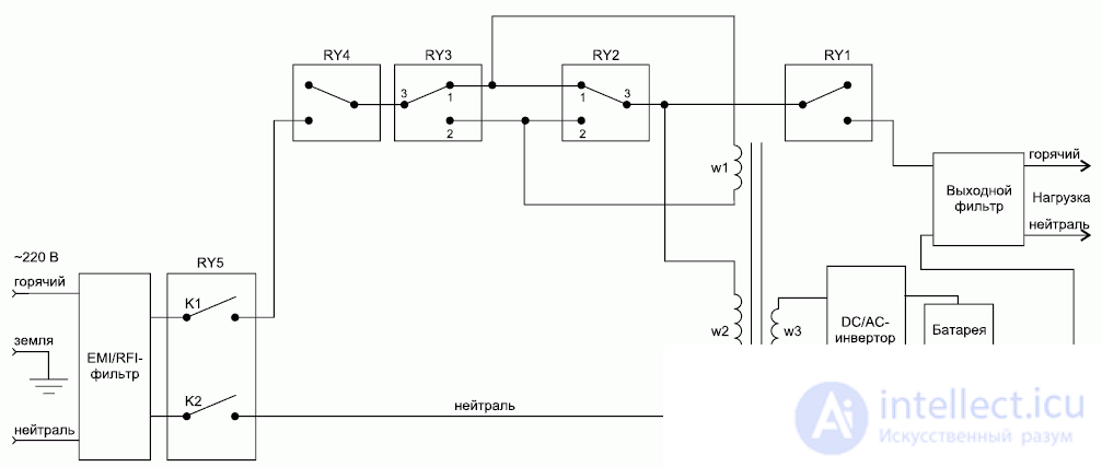
Fig. 4. Block diagram of Smart-UPS and Smart-UPS / VS models
The block diagram of the Smart-UPS and Smart-UPS / VS models is shown in Fig. 4. Mains voltage is supplied to the input EM / RFI filter, which serves to suppress mains interference. At rated voltage, the relays RY5, RY4, RY3 (pins 1, 3), RY2 (pins 1, 3), RY1 are turned on, and the input voltage passes to the load. Relays RY3 and RY2 are used for adjusting the output voltage BOOST / TRIM. For example, if the mains voltage increases and exceeds the permissible limit, relays RY3 and RY2 connect an additional winding W1 in series with the main W2. An autotransformer with a transformation ratio is formed
K = W2 / (W2 + W1)
less than unity, and the output voltage drops. If the mains voltage decreases, the additional winding W1 is reversed by the relay contacts RY3 and RY2. Transformation ratio
K = W2 / (W2 - W1)
becomes greater than unity, and the output voltage rises. The adjustment range is ± 12%, the hysteresis value is selected by the Power Chute program.
When the input voltage fails, the RY2 ... RY5 relays are turned off, a powerful PWM inverter powered by the battery is turned on, and a sinusoidal voltage of 230 V, 50 Hz is supplied to the load.
The multilink filter for suppressing electrical network interference consists of varistors MV1, MV3, MV4, inductor L1, capacitors C14 ... C16 (Fig. 5). The CT1 transformer analyzes the high-frequency components of the mains voltage. The CT2 transformer is a load current sensor. The signals from these sensors, as well as the temperature sensor RTH1, are fed to the analog-to-digital converter IC10 (ADC0838) (Fig. 6).
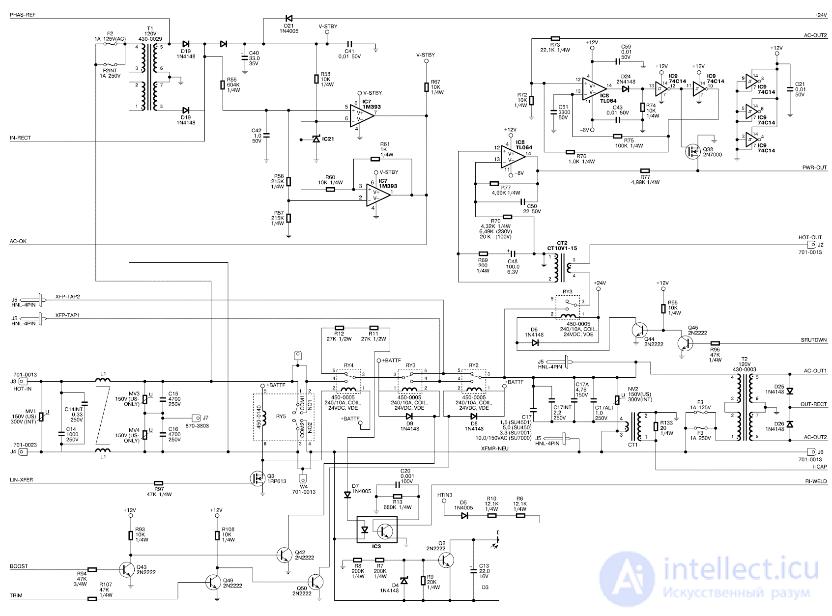
Fig. 5. Input circuits
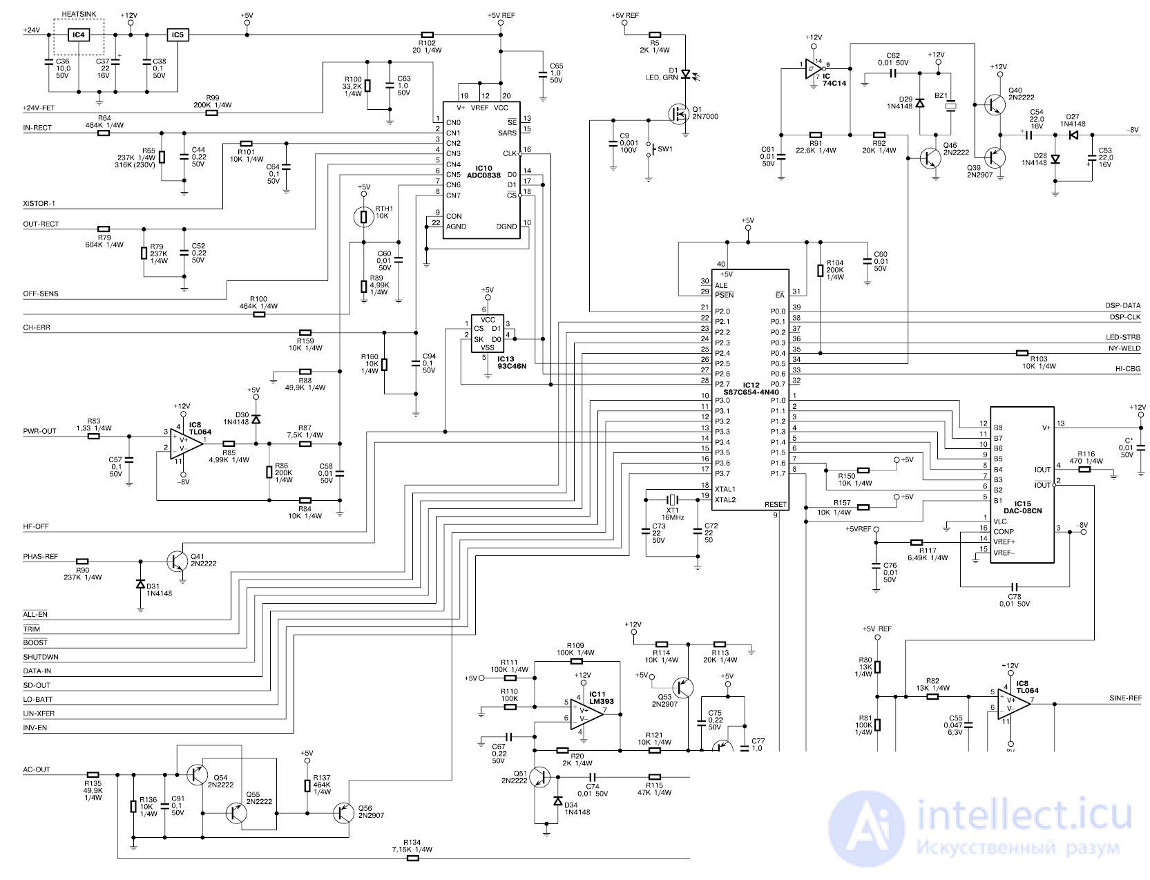
Fig. 6. Turning on the processor
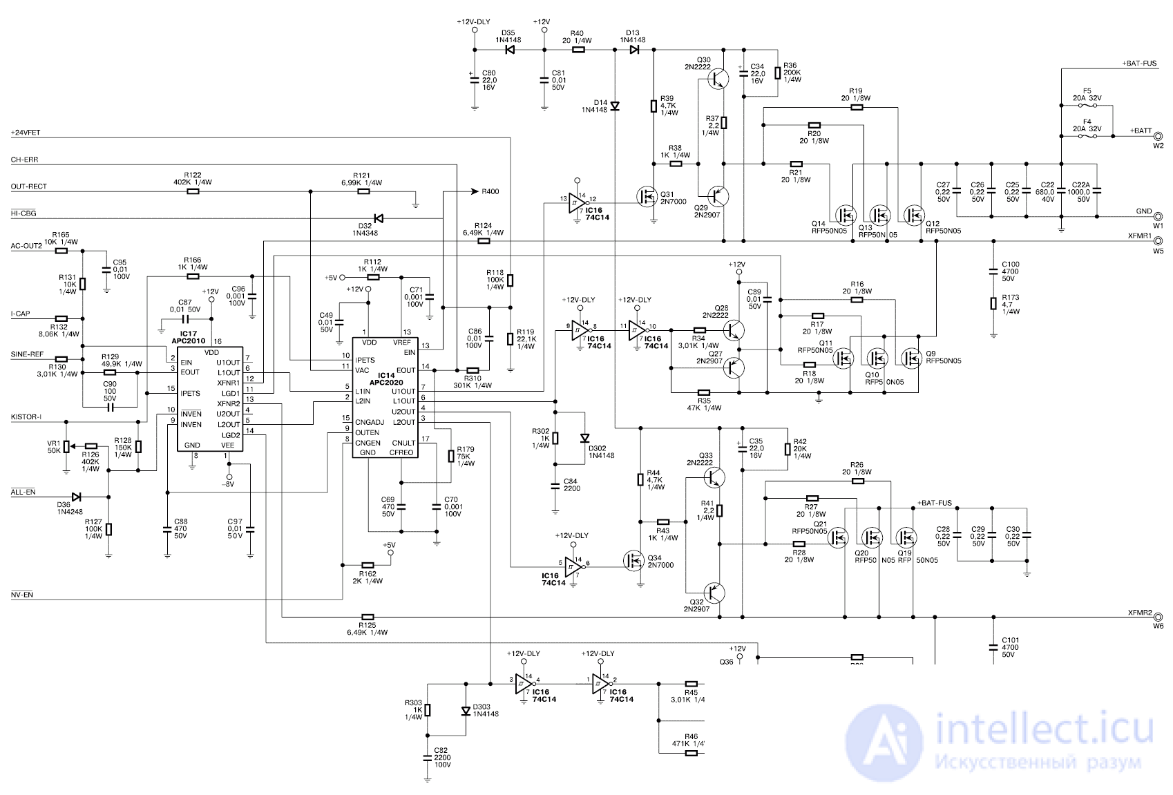
Fig. 7. Output inverter
Transformer T1 is an input voltage sensor. The command to turn on the device (AC-OK) is sent from the two-level comparator IC7 to the Q6 base. Transformer T2 - output voltage sensor for Smart TRIM / BOOST mode. From pins 23 and 24 of processor IC1 2 (Fig. 6), the BOOST and TRIM signals are sent to the bases of transistors Q43 and Q49 to switch relays RY3 and RY2, respectively.
The phase synchronization signal (PHAS-REF) from terminal 5 of transformer T1 goes to the base of transistor Q41 and from its collector to terminal 14 of processor IC12 (Fig. 6).
The Smart-UPS model uses an IC12 microprocessor (S87C654), which:
monitors the presence of voltage in the mains. If it disappears, then the microprocessor connects a powerful inverter running on battery power; turns on a sound signal to notify the user about power problems; provides safe automatic shutdown of the operating system (Netware, Windows NT, OS / 2, Scounix and Unix Ware, Windows 95/98), saving data through a bi-directional switching port when the Power Chute plus program is installed; automatically corrects drops (Smart Boost mode) and excess (Smart Trim mode) of the mains voltage, bringing the output voltage to a safe level without switching to battery operation; controls the battery charge, tests it with a real load and protects it from overcharging, providing continuous charging; provides a battery replacement mode without turning off the power; conducts a self test (every two weeks or by pressing the Power button) and issues a warning about the need to replace the battery; It indicates the level of battery recharge, mains voltage, UPS load (the number of equipment connected to the UPS), the battery mode and the need to replace it.
The EEPROM IC13 memory chip stores factory settings, as well as calibrated settings for frequency signal levels, output voltage, junction boundaries, battery charging voltage.
The digital-to-analog converter IC15 (DAC-08CN) generates a reference sinusoidal signal at pin 2, which is used as a reference signal for IC17 (АРС2010).
The PWM signal is generated by IC14 (APC2020) together with IC17. Powerful field effect transistors Q9 ... Q14, Q19 ... Q24 form a bridge inverter. During the positive half-wave of the PWM signal, Q12 ... Q14 and Q22 ... Q24 are open, and Q19 ... Q21 and Q9 ... Q11 are closed. During the negative half-wave, Q19 ... Q21 and Q9 ... Q11 are open, while Q12 ... Q14 and Q22 ... Q24 are closed. Transistors Q27 ... Q30, Q32, Q33, Q35, Q36 form push-pull drivers that generate control signals of powerful field-effect transistors with a large input capacitance. The load of the inverter is the transformer winding, it is connected by wires W5 (yellow) and W6 (black). A sinusoidal voltage of 230 V, 50 Hz is formed on the secondary winding of the transformer to power the connected equipment.
Inverter operation in “reverse” mode is used to charge the battery with pulsating current during normal operation of the UPS.
The UPS has a built-in SNMP slot, which allows you to connect additional cards to expand the capabilities of the UPS:
Power Net SNMP adapter that supports direct connection to the server in case of emergency shutdown of the system; UPS interface extender for managing up to three servers; Call-UPS remote control for remote modem access.
The UPS has several voltages necessary for the normal operation of the device: 24 V, 12 V, 5 V and -8 V. To check them, you can use the table. 2. The resistance from the terminals of the microcircuits to the common wire should be measured with the UPS turned off and the discharged capacitor C22. Typical UPS Smart-Ups 450VA ... 700VA malfunctions and their solutions are given in table. 3.
Table 2. Voltages at test points
| Voltage | Microchip / output | Common wire resistance | Possible malfunctioning components |
|---|---|---|---|
| 24 V | IC4 / 1 | 1 megohm | C41, C36, C63, IC4, SNMP, display board with flexible cable, fan |
| 12 v | IC4 / 3 | 1 kOhm | IC5, C8, D401, IC2, Q9 ... Q14, Q19 ... Q24 |
| 5 v | IC5 / 3 | 1 kOhm | D402, C65, IC12, IC5, IC10, IC13 (reprogram) |
| -8 V | IC17 / 1 | 15 kOhm | C7, Q39, Q40, C54, C53, D28, D27, IC9, IC17 |
Table 3. Typical UPS Smart-Ups 450VA ... 700VA Faults
| Brief description of the defect | Possible reason | Troubleshooting Method |
|---|---|---|
| UPS does not turn on | No batteries connected | Connect batteries |
| Bad or faulty battery, low capacity | Replace battery. The capacity of a charged battery can be checked by the high beam lamp from the car (12 V, 150 W) | |
| Powerful inverter field effect transistors punched | In this case, there is no voltage at the terminals of the battery connected to the UPS board. Check with an ohmmeter and replace the transistors. Check the resistors in their gate circuits. Replace IC16 | |
| Break in the flexible cable connecting the display | This malfunction may be caused by a short in the flexible cable leads to the UPS chassis. Replace the flexible cable connecting the display to the UPS main board. Check the fuse F3 and transistor Q5 | |
| The power button is sold | Replace SW2 Button | |
| UPS is turned on only by battery | Fuse F3 Blown | Replace F3. Check for transistors Q5 and Q6. |
| UPS does not start. Battery replacement indicator is on | If the battery is OK, then the UPS is not processing the program correctly. | Calibrate the battery voltage using a proprietary program from APC |
| UPS does not turn on line | The network cable is disconnected or the contact is broken | Connect the network cable. Use an ohmmeter to check the condition of the automatic plug. Check Hot-Neutral Cord Connection |
| Cold soldering board elements | Check the serviceability and quality of the rations of the elements L1, L2 and especially T1 | |
| Defective varistors | Check or replace varistors MV1 ... MV4 | |
| When the UPS is turned on, load shedding occurs | Faulty voltage sensor T1 | Replace T1. Check the serviceability of the elements: D18 ... D20, C63 and C10 |
| Display indicators blink | The capacitance of the capacitor C17 decreased | Replace capacitor C17 |
| Capacitor leakage likely | Replace C44 or C52 | |
| Defective relay contacts or circuit board elements | Replace relay. Replace IC3 and D20. D20 is better to replace with 1N4937 | |
| UPS overload | Power of connected equipment exceeds rated | Reduce the load |
| Faulty transformer T2 | Replace t2 | |
| Faulty current sensor CT1 | Replace CT1. Resistance greater than 4 ohms indicates a current sensor malfunction | |
| Faulty IC15 | Replace IC15. Check the voltage of -8 V and 5 V. Check and, if necessary, replace: IC12, IC8, IC17, IC14 and powerful inverter field effect transistors. Check the windings of the power transformer | |
| Battery is not charging | UPS program does not work correctly | Calibrate the battery voltage with a proprietary APC program. Check constants 4, 5, 6, 0. Constant 0 is critical for each UPS model. Do a constant check after replacing the battery |
| Battery Chart Failure | Replace IC14. Check the voltage of 8 V on the pin. 9 IC14, if not, replace C88 or IC17 | |
| Battery defective | Replace battery. Its capacity can be checked with a high beam lamp from the car (12 V, 150 W) | |
| Faulty microprocessor IC12 | Replace IC12 | |
| When turning on, the UPS does not start, a click is heard | Faulty reset circuit | Check serviceability and replace faulty elements: IC11, IC15, Q51 ... Q53, R115, C77 |
| Indicator defect | Faulty indication circuit | Check and replace faulty Q57 ... Q60 on the indicator board |
| UPS does not work on-line | Circuit Board Defect | Replace Q56. Check the condition of the elements: Q55, Q54, IC12. IC13 is defective, or it will have to be reprogrammed. The program can be taken from a working UPS |
| When switching to battery operation, the UPS turns off and turns on spontaneously | Transistor Q3 is broken | Replace Q3 Transistor |
In the second part of the article, an on-line class UPS device will be considered.
UPS DEVICE CLASS OFF-LINE
APC Off-line UPS are Back-UPS models. UPSs of this class are low cost and are designed to protect personal computers, workstations, network equipment, retail and cash registers. The power of the produced Back-UPS models is from 250 to 1250 VA. The main technical data of the most common UPS models are presented in table. 3.
Table 3. Main technical data of Back-UPS class UPS
| Model | BK250I | BK400I | BK600I |
|---|---|---|---|
| Rated input voltage, V | 220 ... 240 | ||
| Nominal frequency of a network, Hz | 50 | ||
| Energy of absorbed emissions, J | 320 | ||
| Peak emission current, A | 6500 | ||
| Normal voltage surges as per IEEE 587 Cat. A 6kVA,% | <1 | ||
| Switching voltage, V | 166 ... 196 | ||
| Output voltage when working on batteries, V | 225 ± 5% | ||
| Output frequency when working on batteries, Hz | 50 ± 3% | ||
| Maximum power, VA (W) | 250 (170) | 400 (250) | 600 (400) |
| Power factor | 0.5. ..1,0 | ||
| Peak factor | <5 | ||
| Nominal switching time, ms | five | ||
| Number of batteries x voltage, V | 2x6 | 1x12 | 2x6 |
| Battery capacity, Ah | 4 | 7 | ten |
| 90% recharge time after discharge up to 50%, hour | 6 | 7 | ten |
| Acoustic noise at a distance of 91 cm from the device, dB | <40 | ||
| UPS operating time at full power, min | > 5 | ||
| Maximum dimensions (H x W x D), mm | 168x119x361 | ||
| Weight, kg | 5,4 | 9.5 | 11.3 |
The “I” (International) index in the UPS model names means that the models are designed for an input voltage of 230 V. The devices are equipped with sealed lead-free maintenance-free batteries with a service life of 3 ... 5 years according to the Euro Bat standard. All models are equipped with limit filters that suppress surges and high-frequency noise of the mains voltage. The devices emit the appropriate sound signals when the input voltage fails, the batteries are discharged, and overload occurs. The threshold voltage value, below which the UPS switches to battery operation, is set by the switches on the back of the device. The BK400I and BK600I models have an interface port that connects to a computer or server for automatic self-closing of the system, a test switch and an audio signal switch.
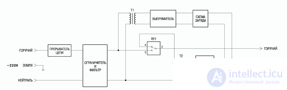
Fig. 8. Block diagram
The back-UPS 250I, 400I, and 600I are shown in Figure 2. 8. Mains voltage is supplied to the input multi-stage filter through a circuit breaker. The circuit breaker is designed as a circuit breaker on the back of the UPS. In the event of a significant overload, it disconnects the device from the network, while the contact column of the switch is pushed up. To turn on the UPS after an overload, it is necessary to reset the contact column of the switch. The input filter-limiter of electromagnetic and radio frequency interference uses LC links and metal oxide varistors. During normal operation, pins 3 and 5 of the RY1 relay are closed, and the UPS transfers power to the load, filtering high-frequency interference. The charging current flows continuously while there is voltage in the network.If the input voltage drops below the set value or disappears altogether, as well as if it is very noisy, contacts 3 and 4 of the relay are closed, and the UPS switches to operation from an inverter, which converts the constant voltage of the batteries into alternating voltage. The switching time is about 5 ms, which is quite acceptable for modern switching power supplies for computers. The waveform at the load is rectangular pulses of positive and negative polarity with a frequency of 50 Hz, a duration of 5 ms, an amplitude of 300 V, an effective voltage of 225 V. At idle, the pulse duration is reduced and the effective output voltage drops to 208 V. Unlike Smart models -UPS, Back-UPS does not have a microprocessor, comparators and logic circuits are used to control the device.and also if it is very noisy, contacts 3 and 4 of the relay close, and the UPS switches to work from an inverter, which converts the constant voltage of the batteries into alternating voltage. The switching time is about 5 ms, which is quite acceptable for modern switching power supplies for computers. The waveform at the load is rectangular pulses of positive and negative polarity with a frequency of 50 Hz, a duration of 5 ms, an amplitude of 300 V, an effective voltage of 225 V. At idle, the pulse duration is reduced and the effective output voltage drops to 208 V. Unlike Smart models -UPS, Back-UPS does not have a microprocessor, comparators and logic circuits are used to control the device.and also if it is very noisy, contacts 3 and 4 of the relay close, and the UPS switches to work from an inverter, which converts the constant voltage of the batteries into alternating voltage. The switching time is about 5 ms, which is quite acceptable for modern switching power supplies for computers. The waveform at the load is rectangular pulses of positive and negative polarity with a frequency of 50 Hz, a duration of 5 ms, an amplitude of 300 V, an effective voltage of 225 V. At idle, the pulse duration is reduced and the effective output voltage drops to 208 V. Unlike Smart models -UPS, Back-UPS does not have a microprocessor, comparators and logic circuits are used to control the device.which converts the constant voltage of the batteries into alternating. The switching time is about 5 ms, which is quite acceptable for modern switching power supplies for computers. The waveform at the load is rectangular pulses of positive and negative polarity with a frequency of 50 Hz, a duration of 5 ms, an amplitude of 300 V, an effective voltage of 225 V. At idle, the pulse duration is reduced and the effective output voltage drops to 208 V. Unlike Smart models -UPS, Back-UPS does not have a microprocessor, comparators and logic circuits are used to control the device.which converts the constant voltage of the batteries into alternating. The switching time is about 5 ms, which is quite acceptable for modern switching power supplies for computers. The waveform at the load is rectangular pulses of positive and negative polarity with a frequency of 50 Hz, a duration of 5 ms, an amplitude of 300 V, an effective voltage of 225 V. At idle, the pulse duration is reduced and the effective output voltage drops to 208 V. Unlike Smart models -UPS, Back-UPS does not have a microprocessor, comparators and logic circuits are used to control the device.5 ms, 300 V amplitude, 225 V effective voltage. At idle, the pulse duration is reduced and the effective output voltage drops to 208 V. Unlike Smart-UPS models, the Back-UPS does not have a microprocessor, comparators and logic chips.5 ms, 300 V amplitude, 225 V effective voltage. At idle, the pulse duration is reduced and the effective output voltage drops to 208 V. Unlike Smart-UPS models, the Back-UPS does not have a microprocessor, comparators and logic chips.
Schematic diagram of the UPS Back-UPS 250I, 400I and 600I is almost completely shown in Fig. 9 ... 11. The multilink filter for suppressing electrical interference consists of varistors MOV2, MOV5, chokes L1 and L2, capacitors C38 and C40 (Fig. 9). Transformer T1 (Fig. 10) is an input voltage sensor. Its output voltage is used to charge the batteries (D4 ... D8, IC1, R9 ... R11, C3 and VR1 are used in this circuit) and to analyze the mains voltage.

Fig. 9. Output inverter

Fig. 10. Input circuits
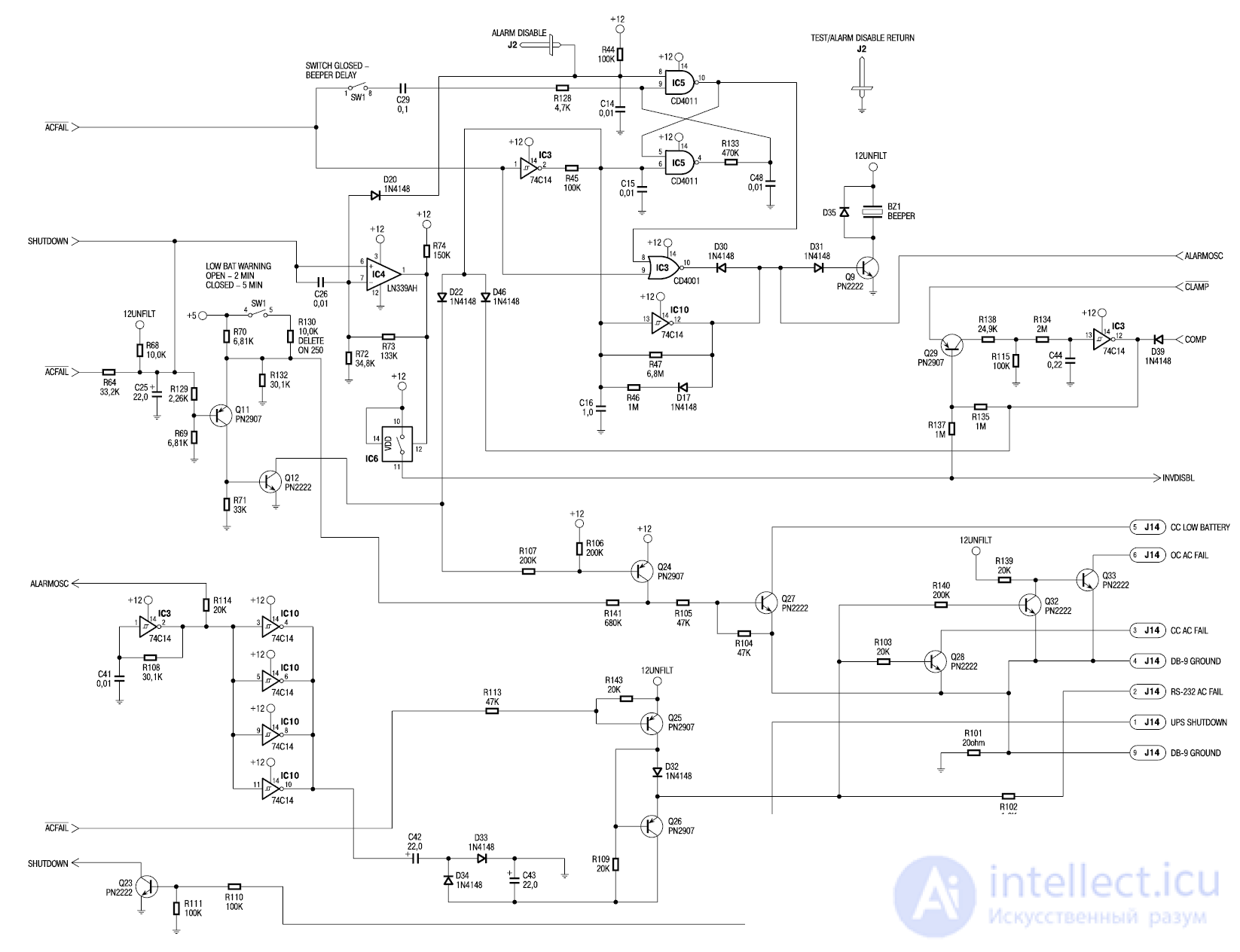
Fig. 11. Management scheme
If it disappears, then the circuit on the elements IC2 ... IC4 and IC7 connects a powerful inverter that runs on battery power. The ACFAIL command for turning on the inverter is formed by IC3 and IC4. The circuit, consisting of a comparator IC4 (pins 6, 7, 1) and an electronic key IC6 (pins 10, 11, 12), allows the inverter to operate with a log signal. “1” to pin 1 and 13 of IC2.
The divider, consisting of resistors R55, R122, R1 23 and switch SW1 (pins 2, 7 and 3, 6), located on the rear side of the UPS, determines the mains voltage, below which the UPS switches to battery power. The factory setting for this voltage is 196 V. In areas characterized by frequent fluctuations in the mains voltage, leading to frequent UPS switching to battery power, the threshold voltage must be set to a lower level. Fine tuning of the threshold voltage is performed by the resistor VR2.
During battery operation, IC7 generates PUSHPL1 and PUSHPL2 inverter excitation pulses. Power transistors Q4 ... Q6 and Q36 are installed in one arm of the inverter, and Q1 ... Q3 and Q37 in the other. With their collectors, transistors are loaded on the output transformer. On the secondary winding of the output transformer, a pulse voltage is generated with an effective value of 225 V and a frequency of 50 Hz, which is used to power the equipment connected to the UPS. The pulse duration is regulated by a variable resistor VR3, and the frequency by a resistor VR4 (Fig. 10). Turning the inverter on and off is synchronized with the mains voltage by the circuit on the elements IC3 (pins 3 ... 6), IC6 (pins 3 ... 5, 6, 8, 9) and IC5 (pins 1 ... 3 and 11 ... 13). The circuit on the elements SW1 (pins 1 and 8), IC5 (pins 4 ... B and 8 ... 10), IC2 (pins 8 ... 10), IC3 (pins 1 and 2),IC10 (pins 12 and 13), D30, D31, D18, Q9, BZ1 (Fig. 11) turns on a sound signal that warns the user about power problems. During battery operation, the UPS emits a single beep every 5 seconds, indicating the need to save user files, as battery capacity is limited. When operating on battery power, the UPS monitors its capacity and provides a continuous sound signal for a certain amount of time before discharge. If pins 4 and 5 of switch SW1 are open, then this time is 2 minutes; if closed, 5 minutes. To turn off the sound signal, it is necessary to close the terminals 1 and 8 of switch SW1.indicating the need to save user files, as battery capacity is limited. When operating on battery power, the UPS monitors its capacity and provides a continuous sound signal for a certain amount of time before discharge. If conclusions 4 and 5 of switch SW1 are open, then this time is 2 minutes, if closed - 5 minutes. To turn off the sound signal, it is necessary to close the terminals 1 and 8 of switch SW1.indicating the need to save user files, as battery capacity is limited. When operating on battery power, the UPS monitors its capacity and provides a continuous sound signal for a certain amount of time before discharge. If conclusions 4 and 5 of switch SW1 are open, then this time is 2 minutes, if closed - 5 minutes. To turn off the sound signal, it is necessary to close the terminals 1 and 8 of switch SW1.
All Back-UPS models, with the exception of the BK250I, have a bi-directional communication port for connecting to a PC. Power Chute Plus software allows the computer to carry out both current UPS control and safe automatic shutdown of the operating system (Novell, Netware, Windows NT, IBM OS / 2, Lan Server, Scounix and UnixWare, Windows 95/98), saving user files. In fig. 11 this port is designated as J14. Purpose of its conclusions:
1 - UPS SHUTDOWN. The UPS shuts down if a log appears on this pin. "1" for 0.5 s.
2 - AC FAIL. When switching to battery power, the UPS generates a log on this pin. "1".
3 - SS AC FAIL. When switching to battery power, the UPS generates a log on this pin. "0". Open collector output.
4, 9 - DB-9 GROUND. Common wire for input / output signals. The output has a resistance of 20 ohms relative to the common UPS wire.
5 - SS LOW BATTERY. In the event of a battery discharge, the UPS generates a log on this pin. "0". Open collector output.
6 - AC FAIL OS When switching to battery power, the UPS generates a log on this pin. "1". Open collector output.
7, 8 - not connected.
Open collector outputs can be connected to TTL circuits. Their load capacity is up to 50 mA, 40 V. If you need to connect a relay to them, then the winding should be shunted with a diode.
The usual "null-modem" cable for communication with this port is not suitable, the corresponding RS-232 interface cable with a 9-pin connector is supplied with the software.
UPS CALIBRATION AND REPAIR
Setting the output voltage frequency
To set the frequency of the output voltage, connect an oscilloscope or frequency meter to the output of the UPS. Turn on the UPS in battery mode. By measuring the frequency at the output of the UPS, adjust the VR4 resistor to set 50 ± 0.6 Hz.
Setting the output voltage
Turn on the UPS in battery mode without load. Connect a voltmeter to the output of the UPS to measure the effective voltage value. Adjust the VR3 resistor to set the output voltage of the UPS to 208 ± 2 V.
Threshold voltage setting
Set switches 2 and 3 on the rear of the UPS to OFF. Connect the UPS to a LATR type transformer with continuously adjustable output voltage. At the LATR output, set the voltage to 196 V. Turn the VR2 resistor fully counterclockwise, then slowly turn the VR2 resistor clockwise until the UPS transfers to battery power.
Charge voltage setting
Set the input voltage of the UPS 230 V. Disconnect the red wire that goes to the positive terminal of the battery. Using a digital voltmeter, adjust the resistor VR1 to establish a voltage of 13.76 ± 0.2 V on this wire relative to the common point of the circuit, then reconnect to the battery.
Typical Malfunctions
Typical malfunctions and methods for their elimination are given in table. 4, and in table. 5 - analogues of the most frequently malfunctioning components.
Table 4. Typical Back-UPS 250I, 400I, and 600I UPS Faults
| Defect manifestation | Possible reason | Method for finding and eliminating a defect |
|---|---|---|
| Smoke smell, UPS not working | Input filter defective | Check the health of the components MOV2, MOV5, L1, L2, C38, C40, as well as the conductors of the board connecting them |
| UPS does not turn on. LED is off | UPS input circuit breaker (circuit breaker) disconnected | Reduce the load of the UPS by turning off part of the equipment, and then turn on the circuit breaker by pressing the contact bar of the circuit breaker |
| Bad battery batteries | Replace batteries | |
| Incorrectly connected batteries | Check battery connection | |
| Inverter faulty | Check the health of the inverter. To do this, disconnect the UPS from the AC mains, disconnect the batteries and discharge the capacitance C3 with a 100 Ohm resistor, ring the drain-source channels of powerful field-effect transistors Q1 ... Q6, Q37, Q36 with an ohmmeter. If the resistance is several ohms or less, then replace the transistors. Check the resistors in the gates R1 ... R3, R6 ... R8, R147, R148. Check the operation of transistors Q30, Q31 and diodes D36 ... D38 and D41. Check fuses F1 and F2 | |
| Replace IC2 | ||
| When turned on, the UPS disconnects the load. | Faulty transformer T1 | Check the operability of the windings of the transformer T1. Check the tracks on the board connecting the T1 windings. Check fuse F3 |
| The UPS is operating on battery power even though there is voltage | Mains voltage is very low or distorted | Check the input voltage with an indicator or a meter. If permissible for the load, reduce the sensitivity of the UPS, i.e. change the limit of operation using the switches located on the back of the device |
| The UPS turns on but no voltage is being supplied to the load. | Faulty relay RY1 | Check the health of relay RY1 and transistor Q10 (BUZ71). Check the health of IC4 and IC3 and the voltage at their terminals |
| Check the tracks on the board connecting the relay contacts | ||
| The UPS buzzes and / or cuts off the load without providing the expected backup time | Faulty inverter or one of its elements | See sub-item “Inverter defective” |
| The UPS does not provide the expected backup time. | Batteries discharged or lost capacity | Charge the batteries. They require recharging after prolonged blackouts. In addition, batteries age quickly with frequent use or when operating in high temperature environments. If the battery is nearing the end of its useful life, it is advisable to replace them, even if the alarm does not sound the battery replacement. The capacity of a charged battery is checked by a car high beam lamp 12 V, 150 W |
| UPS is overloaded | Reduce the number of consumers at the output of the UPS | |
| UPS does not turn on after replacing batteries | Incorrect battery connection when replacing them | Check if the batteries are connected correctly. |
| When turned on, the UPS emits a loud tone, sometimes with a decreasing tone. | Bad or badly discharged batteries | Charge the batteries for at least four hours. If the problem persists after recharging, replace the batteries. |
| Batteries do not charge | Faulty diode D8 | Check if D8 is working. Its reverse current should not exceed 10 μA |
| Charge voltage below required level | Calibrate battery voltage |
Table 5. Analogs for Replacing Defective Components
| Circuit designation | Malfunctioning component | Possible replacement |
|---|---|---|
| IC1 | LM317T | LM117H, LM117K |
| IC2 | CD4001 | K561LE5 |
| IC3, IC10 | 74C14 | It is composed of two K561TL1 microcircuits, the conclusions of which are connected according to the pinout on the microcircuit |
| IC4 | LM339 | K1401CA1 |
| IC5 | Cd4011 | K561LA7 |
| IC6 | CD4066 | K561KT3 |
| D4 ... D8, D47, D25 ... D28 | 1N4005 | 1N4006, 1N4007, BY126, BY127, BY133, BY134, 1N5618 ... 1N5622, 1N4937 |
| Q10 | BUZ71 | BUZ10, 2SK673, 2SK971, BUK442 ... BUK450, BUK543 ... BUK550 |
| Q22 | IRF743 | IRF742, MTP10N35, MTP10N40, 2SK554, 2SK555 |
| Q8, Q21, Q35, Q31, Q12, Q9, Q27, Q28, Q32, Q33 | PN2222 | 2N2222, BS540, BS541, BSW61 ... BSW 64, 2N4014 |
| Q11, Q29, Q25, Q26, Q24 | PN2907 | 2N2907, 2N4026 ... 2N4029 |
| Q1 ... Q6, Q36, Q37 | IRFZ42 | BUZ11, BUZ12, PRFZ42 |
Gennady Yablonin
"Repair of electronic equipment"
Useful links on the topic of repair:
продолжение следует...
Часть 1 Design and repair of uninterruptible power supply company ARS

Comments
To leave a comment
Diagnostics, maintenance and repair of electronic and radio equipment
Terms: Diagnostics, maintenance and repair of electronic and radio equipment