Lecture
The process of troubleshooting devices is a collection of elementary checks, i.e. Physical experiments on the repaired device, determined by the value of the impact that is applied to the device, as well as its response to this impact. It is possible to detect a malfunction only if there is such a test effect, the response to which is different for an operational and non-operational device. In the general case, there may be several elementary checks that allow to identify a certain technical condition of the device. They differ in the set of control points, the type and sequence of input test effects.
The variety of the possibilities listed above makes it necessary to formalize the development of the troubleshooting process in the device. The first stage of formalization presupposes the presence of some description of the repaired device and its behavior in working and non-working conditions.
Such a formal description in analytical, vector, graphical or tabular forms is called the mathematical model of the repaired device.
Any device, including a radio measuring device, is characterized by the dependence of the set of output parameters Y = {Y k } on the set of input X = {X k } and internal A = {A k } variables. The behavior of the device model generally depends on the time V.
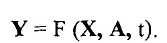 (one)
(one)
Such a record represents the transfer functions of a functioning device.
A malfunction that occurs in the device leads to a distortion of the transfer functions, characterized by many models of an inoperative object:
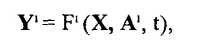 (2)
(2)
where i = 1, 2, 3, ... M - numbers of faulty states.
Often, only the model of a working device is explicitly specified, and models (2) are to be developed. For most complex devices, it is usually not possible to construct a model (2) using only external nodes — the main inputs and outputs. Therefore, the system of equations (2) usually should include a description of the internal, electrical, and time dependencies found on an extended set of functional nodes.
Let us denote the set of all admissible elementary checks of the repaired device P = {Pj} - We will assume as valid all physically feasible elementary checks when troubleshooting. Each check is characterized by the value of the impact applied to the repaired device, the composition of the control points and the value of the device's reactions to these impacts.
In general, the number of possible test results is determined by the number of control points in the device and the number of impacts on it.
Responses of Rj to X ; input effects for operable (3) and inoperative (4) devices are determined by the equations:

Elementary checks allow detecting any state from the set of inoperative states S HP devices, if there is at least one check P for which the responses of the operable Rj and the inoperative Rj 1 device are different, i.e. Rj Φ Rj 1 .
To develop a troubleshooting procedure, it is necessary to obtain a set of reactions for all admissible elementary checks and select those checks from the set {Pj}, which allow distinguishing all states from the set of technical states of device S.
The process of troubleshooting in this case requires a deep analysis of measurement results, a large number of computational operations and multiple comparison of their results.
The process of finding faults in a device becomes much more complicated, therefore, analytical methods for developing this process in devices have found application in cases when devices are simple in terms of circuit design and the power of many technical states S is limited (for example, only with single faults), and elementary checks are performed using of the same type of input effects.
The tabular model of the device is simpler, more visual and convenient in the analysis and development of the troubleshooting procedure.
A table showing the device's reactions to all permissible elementary calibrations for the entire set of possible technical states is called the device malfunction function table (TFN). It is a universal mathematical model of the device. The assignment of TFN is equivalent to the assignment of models (2) and (3). One such TFN is given in table 1.1.
Table 1.1. Example of device fault function table
Technical condition | S, | s 2 | s 3 | S k | ||
Elementary checks | Preset reaction | R. | Rj | Rs | Rn | |
R, | REU reaction to P, | r 2 | R4 | Re | Rm | |
p 2 | REU reaction onR 2 | r 7 | Rj | r 5 | Rk | |
RP | REU reaction to Р „ | Ri | Rj | Rs | Rn | |
The analysis of the above-mentioned DFN shows that the elementary checks of P, and P 9 allow to establish the fact of the presence of malfunctions in the electronic device, since on an elementary check P, the response does not coincide with the reactions of a workable REU given in the table, i.e. 
After the repair of the RGU, the second elementary check P 2 established that th <  , but
, but 
After repeated repair (if necessary adjustment) P p elementary check did not allow to identify the distinctiveness of the specified Rj and response reactions, i.e.  So
So
Thus, after repairing and adjusting the device, its technical condition became operational.
Many elementary checks can detect faults in devices. One of the tasks of optimizing the troubleshooting process is to reduce the number of elementary checks that provide the required depth of troubleshooting.
When carrying out repairs of radio-measuring devices, the specialist who carries out its repairs must build a TFN on the basis of the tables, usually given in the annexes to the instructions for the use of devices, technical passports and other documents. An example of such TFN is given in table 1.2.
Table 1.2. Fault table of electronic module fragment
Measured Parameters | VT1 Voltage, V | VT2 - Voltage, V | VT3 Voltage, V | |||||||
Control points | TO | Uh | B | TO | Uh | B | TO | Uh | B | |
Preset reaction | -0.6 | +2.85 | +2.2 | +0.6 | -6,3 | -0.9 | +0.4 | +3.9 | +3.0 | |
R, | Measured | -0,58 | + M | +2.5 | +0.63 | -6,1 | -1.5 | +11.5 | +0,1 | +0.015 |
P 2 | Measured | -0.59 | +2.79 | +2,1 | +0.59 | -5,8 | -0.92 | +0.43 | +3.7 | +2.9 |
The first elementary test (P,) established the difference in all responses in the control of constant voltages at the terminals of transistors VT1 (E) and VT2 (B), i.e. established the presence of faults.
After a detailed analysis of the causes of the discrepancies obtained in the measurement results, localization and troubleshooting, a second elementary test was carried out, which did not allow us to obtain a difference in the specified and response reactions when monitoring constant voltages at the terminals of the VT1 - VT3 transistors.
Often in the annexes to the instructions for the use of radio-measuring devices in the tables, except for constant (alternating) voltages, resistance values of resistors, diagrams of voltages at the terminals of transistors, microcircuits or at characteristic control points of the concept are also given.
Note that if the NTD does not specify tolerances for the deviation of the specified voltages, then they are usually taken equal to + 20% from the values specified in the tables.
In most cases, if constant voltages at the terminals of transistors, microcircuits, and other elements are in the tolerance zones, then the device is most likely operational.
In cases where the constant voltages are normal and the electrical signal at the output of the device is still absent, then faults should be sought in the input (matching) transformers, separation capacitors (due to breaks in their plates), hidden installation defects (SDM) and etc.

Comments
To leave a comment
Diagnostics, maintenance and repair of electronic and radio equipment
Terms: Diagnostics, maintenance and repair of electronic and radio equipment