3.3.1 STRUCTURAL SCHEME OF MATTIC PRINTER AND ITS FEATURES. TROUBLESHOOTING AND REPAIRING THE MATRIX PRINTER

Lecture


The matrix printer (MP) is a complex microprocessor electronic-mechanical device, assembled on a modern electronic base using optoelectronics, stepper motors (SD), an electromechanical drive.

The matrix printer implements a shock method of image registration.

3.3.1 STRUCTURAL SCHEME OF MATTIC PRINTER AND ITS FEATURES.  TROUBLESHOOTING AND REPAIRING THE MATRIX PRINTER
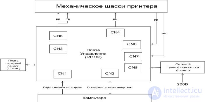
Figure 73 - Matrix Printer Block Diagram

The main components of the printer and their relationship are shown in Figure 72.

  • mechanical chassis of the printer;
  • ROCX - main electrical board (control board);
  • LCPNL - front panel board;
  • PF - stepper motor paper feed;
  • CR - carriage stepping motor;
  • PH - printhead (PG) '.
  • RE - paper end sensor;
  • HP - carriage left edge sensor;
  • CN1 - 36-pin parallel interface connector;
  • CN2 - 26-pin serial interface connector;
  • CN3 - 9-pin connector for receiving signals from the front panel buttons and output signals for controlling LEDs;
  • CN4 - 12-pin connector for printhead control output signals;
  • CN5 - 12-pin connector for output control signals for carriage stepper motors and paper feed;
  • CN6 - 2-pin connector for receiving a signal from the paper end sensor;
  • CN7 - 2-pin connector for receiving a signal from the sensor of the left edge of the carriage pass;
  • CN8 - 4-pin connector for input supply voltages.

Diagnostics of malfunctions and repair of the matrix printer

To initialize the printer, you must either turn on the power switch, or send an L-level RESET signal via the interface cable.

When the printer is initialized, the following actions occur:

  • the carriage is set to the position HOME;
  • ON LINE is set;
  • all buffers are cleared;
  • set line spacing 1/6 ";
  • set the page length to 11 or 12 inches, according to the position of the DIP switches;
  • all vertical tabs are cleared, and horizontal tabs are set for every 8 columns;
  • The print mode is set according to the position of the DIP switches.

Sound alarm
Buzzer buzzers inform the operator about the following events:

  • the arrival of the BEL command to the printer, while the buzzer beeps once (the duration of the sound signal is about 0.1 s);
  • installing the font NLQ-Roman, while the buzzer beeps twice;
  • installing the NLQ-Sans-Serif font, while the buzzer beeps three times;
  • installing the DRAFT font, the buzzer beeps once;
  • SelecType mode selection, while the buzzer beeps once;
  • the end of the paper, with the buzzer buzzing 8 times;
  • abnormal carriage movement, while the buzzer beeps 5 times;
  • the deviation of the supply voltage from the allowable values, while the buzzer hums 5 times.

The printer goes into an alarm state when:

  • not detecting the left edge of the carriage pass during initialization (Home Position);
  • exceeding the voltage of +24 V, powering the SD and PG, magnitudes +27 V.

Troubleshooting should be carried out from simpler elements to more complex and costly according to a predetermined plan. The method of successive exclusion of components suspected of failure is preferred, if there are obviously corrected components for replacement. Failures in electronic components are usually quite simple. The causes of faults are most often:

  • “Breakdown” on the ground or on the power cable of the output of the chip;
  • lack of contact or breakage of the contact conductor on the chip;
  • defective logical levels;
  • "Care" of parameters of transistors, registers, capacitors;
  • wrong voltage level;

violation of the timing diagram of the node or component.

Printer lubrication

EPSON recommends that parts at the points shown in the figure be lubricated according to schedule using lubricants that have been tested over a wide range and that meet the requirements of a printing device.

It is necessary to regularly lubricate at intervals A and B in the table. You must ensure that the parts called are clean before applying the lubricant, and avoid over-applying, which can damage the connected parts.

No

Lubrication points

Lubricant

Interval

one*

The contact part of the shaft of the pulley belt drive and E-

G-27

AT

rings

2 *

The contact part of the planetary gear painting

G-27

AT

tape and shaft

3 *

The contact part of the drive ribbon drive and

G-27

AT

shaft

four*

Contact part of the paper feed roll and shaft

G-27

AT

five*

Felt

0-2

BUT

6 *

Carriage guide axis

0-2

BUT

7 *

Paper Reduction Gear Shaft

G-14

AT

eight*

Reducing gear of paper feed (1/3 of perimeter)

G-14

AT

Note.

* - lubrication is required during the assembly process.

A - grease every six months.
B - lubrication at every major overhaul.

3.3.1 STRUCTURAL SCHEME OF MATTIC PRINTER AND ITS FEATURES.  TROUBLESHOOTING AND REPAIRING THE MATRIX PRINTER
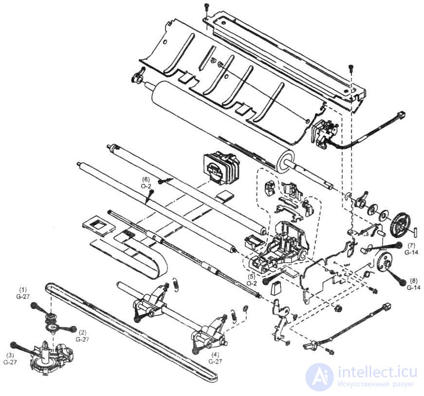
Figure 74 - Diagram of disassembly of the matrix printer and the location of lubrication points


Comments


To leave a comment
If you have any suggestion, idea, thanks or comment, feel free to write. We really value feedback and are glad to hear your opinion.
To reply

Diagnostics, maintenance and repair of electronic and radio equipment

Terms: Diagnostics, maintenance and repair of electronic and radio equipment