Lecture
the beginning of repair -> analysis of the external manifestation of malfunction -> study of the principle of operation of the device -> (according to the electrical structural diagram of E3; according to the electrical installation scheme) -> determination of the most probable faulty blocks -> study of the relationship between the most probable faulty blocks -> visual inspection of suspected block malfunction -> selection of the fault finding method -> development of the fault finding algorithm -> construction of a mathematical model for the malfunctioning block -> control of fixed (variable) voltages in the faulty unit -> analysis of the results of stress control -> identification of identified faults in the units -> performance monitoring and adjustment -> registration of the results of repair and adjustment of the device -> end.
The REA scheme, performed at any level of division into elements, reflects the electrical and electromagnetic processes occurring in a serviceable device. If the scheme takes into account all the relationships between the batteries and signal conversion, then it can serve both to study the operating principles of REA, and to search for faults, which are collectively referred to as “breaks”.
A break is understood to mean any deterioration or termination of any element that does not trigger the protective device against overloads and does not cause changes in the supply voltages in REA circuits. An open circuit could be a physical open circuit or any obstacle to the passage of signals.
In case of failures of the "break" type, the search task is resolved successfully, if an element is found, at the inputs of which signals and power are present, and there is no signal at the output (or it is greatly distorted or changed).
Overload failures occur when an overload or short circuit occurs in a component circuit or in a power supply circuit. When this occurs, the operation of the protective device. Therefore, the search sequence leads to the localization of the activated protective device.
When a short circuit in the element receiving power, the resistance of the circuit sharply decreases, resulting in a shunting of the power supply circuit, and the current in it increases. The closest protection device trips.
When finding faults in the RIP, you can use the technological scheme of control and troubleshooting, shown in Fig. 1.1
At the top of the flow chart, an external fault is indicated, for example, “there is no beam on the screen of the cathode ray tube (CRT) of the oscilloscope”, “the beam does not move vertically”, “there is no sinusoidal signal at the output of the low frequency generator”, etc.
At the first stage, the specialist who carries out the repair of the device studies the principle of operation of the device according to electrical circuits: structural, principal and assembly.
After studying the relationships between the most probable faulty units (modules) of the device, they conduct a visual inspection of the suspected faulty units (modules). If visual inspection revealed, for example, charred resistors, swollen electrolytic capacitors, mechanical damage to ceramic capacitors, and other defects, these elements are replaced with obviously workable ones. If visual inspection did not reveal any inoperable items, then a specialist, depending on the type of fault, selects fault finding methods and draws up an algorithm for finding them.
It should be noted that if the algorithm compiled and implemented in practice did not allow detecting malfunctions in the equipment, this suggests that the specialist is not sufficiently complete
The principle of its operation and the methods of troubleshooting in blocks (modules) or in equipment as a whole have been studied.
At the next stage, the construction of a table of fault functions for an electronic device (REU) is carried out. It is a table in which the values of static (constant) and dynamic (variable) parameters (voltages, currents, etc.) are recorded in the characteristic control points of the circuit of the repaired device. It should be remembered that constant voltages determine the mode of operation of individual cascades in the circuit of the repaired unit (module). In more detail the methodology for developing the model of the repaired device is described in section 1.3.
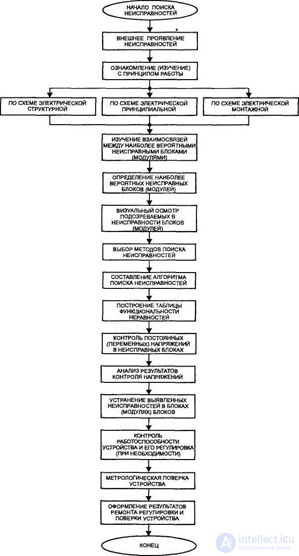
After the model is compiled in accordance with the chosen methods and algorithm, faults in the REU are identified and eliminated.
At the next stage of work, the device’s performance is monitored and, according to its results, if necessary, adjustments are made (complex adjustment).
Since radio measuring devices are used to measure the parameters (characteristics) of various types of electronic devices, they must, after repair and adjustment, undergo a metrological calibration.

Comments
To leave a comment
Diagnostics, maintenance and repair of electronic and radio equipment
Terms: Diagnostics, maintenance and repair of electronic and radio equipment