Lecture
As a characteristic malfunction of the power supply circuit of the 5STX board, we can note the failure of the U11 PWM controller chip — HIP6008CB. The board does not start, but on closer examination, the absence of the core voltage is determined. You can verify the malfunction of the chip by observing the absence of a PWM signal at pin 12 by using an oscilloscope.
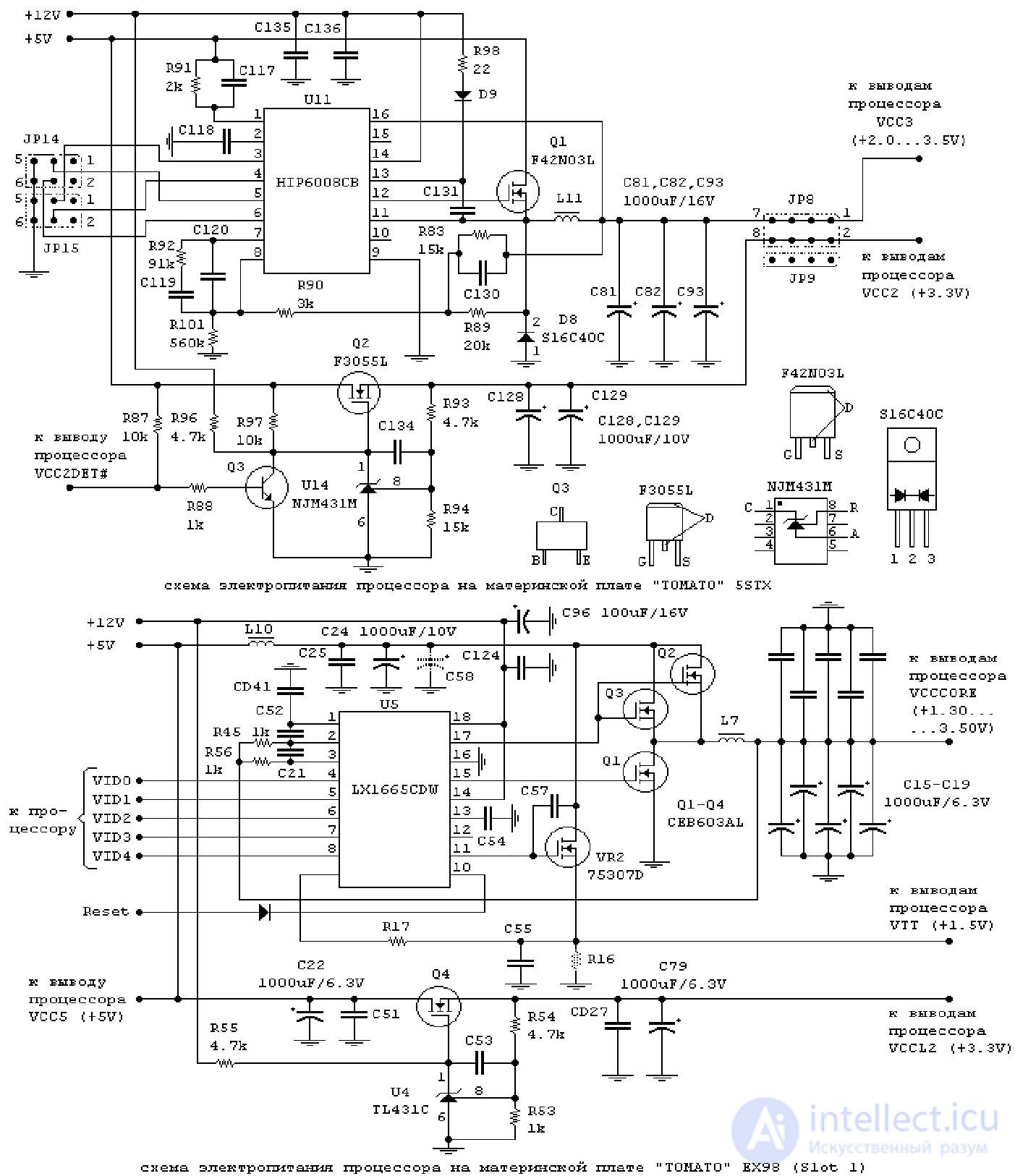
As an example of the failure of the power supply circuit of the EX98 board, we can note the failure, literally “burnout”, of the parallel-connected transistors Q2 and Q3 of CEB603AL. The performance of the board with such a defect was restored by replacing the faulty transistors with serviceable RFP50N06 (full name RFP50N06LE) manufactured by HARRIS with the following parameters: Usi = 60 V; IC = 50 A; rsi = 0.022 Ohm; built-in diode between the drain and source; housing TO-220AB [1].
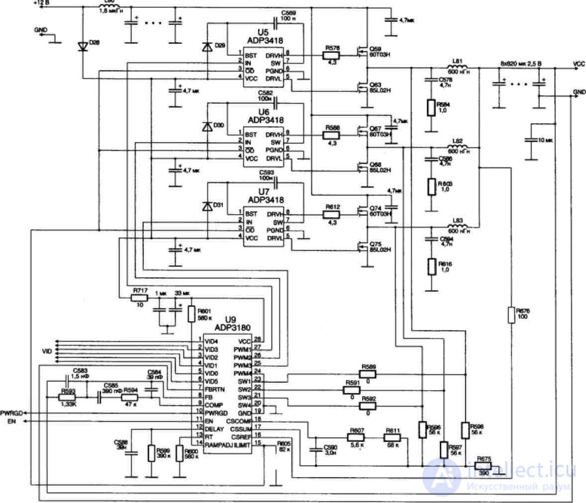
The ADP3180 IC also provides a special Power Good signal (pin 10), a high level of which indicates that the output voltage level lies in the range from -250 mV to +150 mV relative to the nominal one. When these limits are exceeded, the corresponding comparator is triggered, the signal from which is fed to the input of the logic circuit that forms the Power Good signal. When the nominal voltage is exceeded by 150 mV, an internal CROWBAR signal is issued, according to which the channel control logic opens the lower keys of the half-bridges, which ultimately leads to a decrease in the output voltage. Thus, overvoltage protection is implemented.
A typical malfunction is a failure of the upper arm transistor of one of the half-bridges, and this transistor may be broken. In this case, when you turn on the computer's power, the voltage of 12 V is fed directly to the processor. The current consumption increases dramatically, current protection is activated in the power supply unit of the computer. This happens almost instantly: the fan blades only manage to move a little. In this case, in no case should you try to turn on the power several times, and even more so turn on the motherboard without a processor - all this is fraught with burning out in the literal sense of the word with all the attendant effects (smoke, flame) of some elements on the motherboard. The specified 60TOZN transistor manufactured by the Taiwanese company Advanced Power Electronics Corp (Usi = 30 V, Ic = 60 A, Rsi = 12 m0m) can be replaced by the very common IRF3205 (Usi = 55 V, Ic = 110 A, Rsi = 8 m0m) produced by the company
International Rectifier.
However, if the power supply to the motherboard is supplied correctly, but there is no voltage on the processor, you should start troubleshooting.
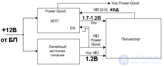
First of all, you should check the voltage level at the EN input (pin 11) of the PWM controller. He must be tall. It may well be that the PWM controller simply does not turn on due to the fact that the motherboard circuit blocks the inclusion of the IPP. The fact is that until the value of the VID code is set, the API should not be included. A special linear power supply with a voltage of 1.2 V is used to power the processor circuit issuing the digital VID code.
Further troubleshooting and repair is carried out using a schematic diagram (Figure 2). Most IPPs of modern motherboards, even for Pentium 4 processors in a 775-pin package, are almost indistinguishable from the one reviewed.

Comments
To leave a comment
Diagnostics, maintenance and repair of electronic and radio equipment
Terms: Diagnostics, maintenance and repair of electronic and radio equipment