Lecture

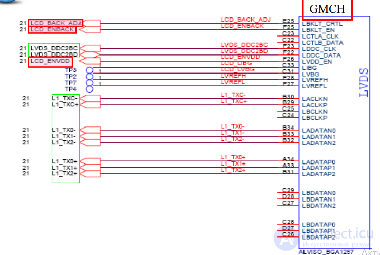

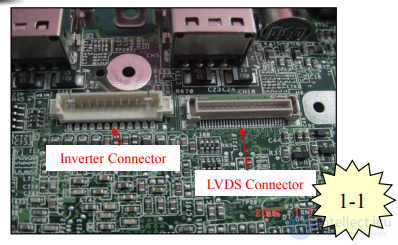
LVDS Connector
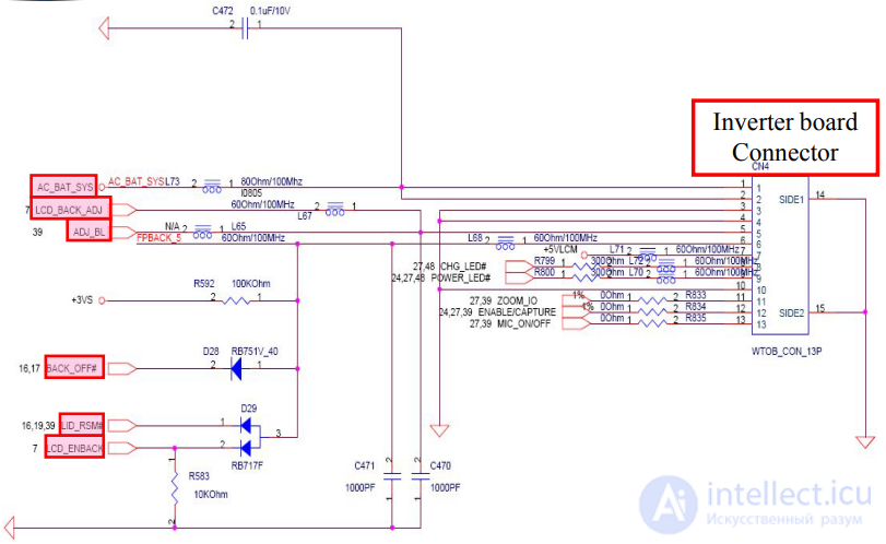
Inverter board Connector
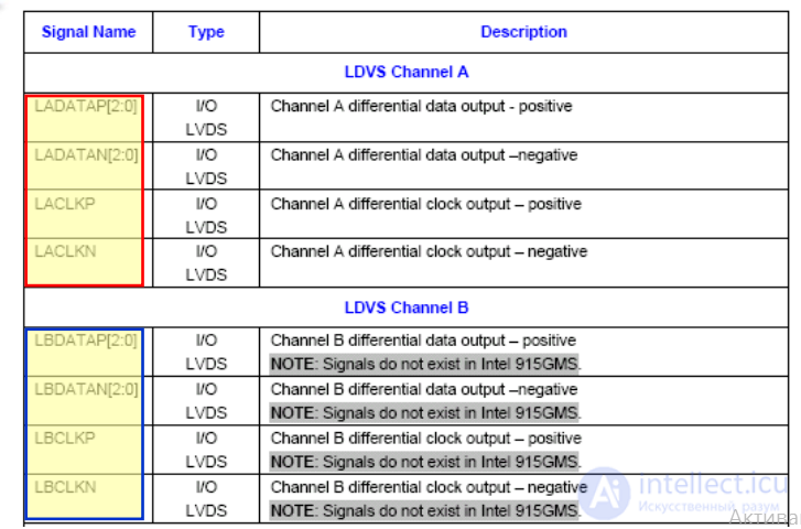
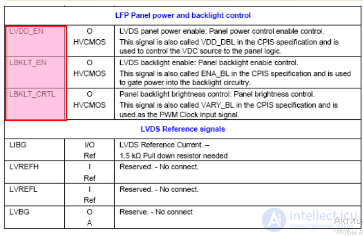
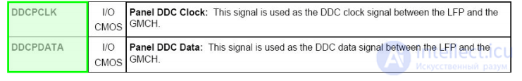
Signal Define
LVDS is short for "Low Voltage Differential Signaling" and is a high speed, low power data transmission standard. LVDS is standardized in the ANSI/TIA/EIA-644-1995 Electrical characteristics standard titled: "Electrical Characteristics of Low Voltage Differential Signaling (LVDS) Interface Circuits“ The LVDS standard is an electrical standard only defining driver output characteristics and receiver input characteristics. Guideline are also given on bus configuration, cables, and termination. Protocol, connectors, and bus structure is not defined in this standard, as they are application dependant. It is intended that these parameters are specified by the referencing standard
LVDS is envisioned to be forward looking and does not define a maximum data rate within the standard. As maximum data rate is design, technology, and application dependant (required signal quality). Current LVDS parts operate from DC to Giga bits per second range.
Power dissipation is minimized in a number of ways. This includes the CMOS process, the current mode driver design, and also the small load current
. Noise generation is minimized in a number of ways. The signal swing is only 300mV, and also a true balanced differential data transmission scheme, and the current mode driver all limit noise generation.

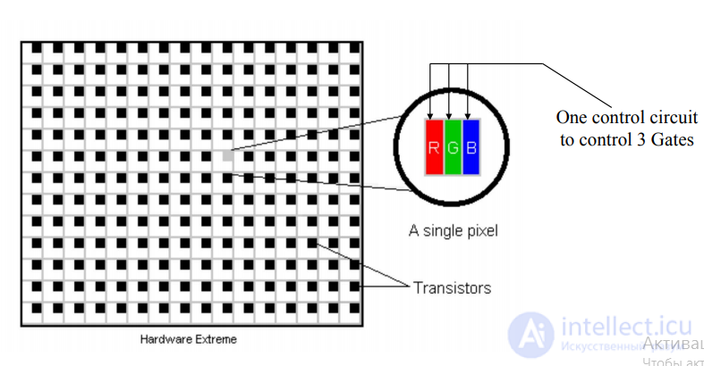
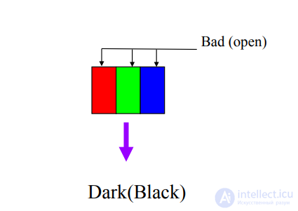
Bright & Dark Pixel #1

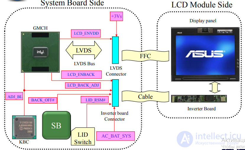
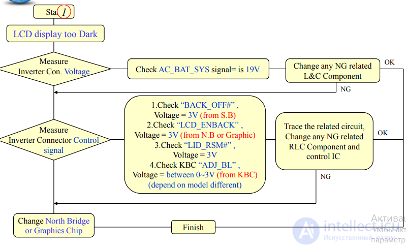
Block Diagram Flow Diagnostics and Troubleshooting LCD Matrix

Visual Inspection 1.check Inverter/LVDS connector is no NG or BAD solder 2.R.L.C. components & Trace is no damage or miss or open
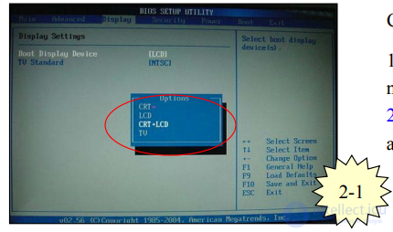
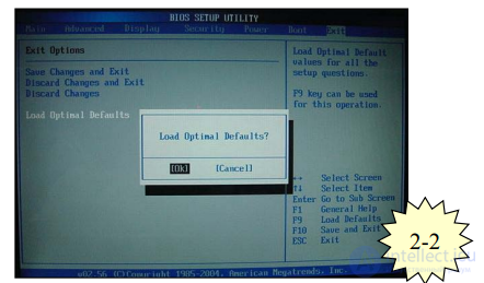
Check BIOS Setting: 1.Check display mode is OK, not only CRT mode 2.Load BIOS default setting and test again
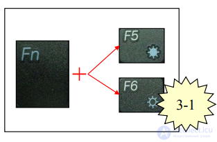
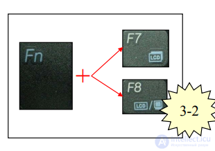
Check Fn Key Setting: 1.Fn + F5 is brightness Down 2.Fn + F6 is brightness Up 3.Fn + F7 is LCD Back Light On/Off 4.Fn + F8 is LCD/CRT/TV Mode switching (all function key is depend on designer)
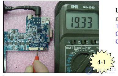
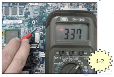
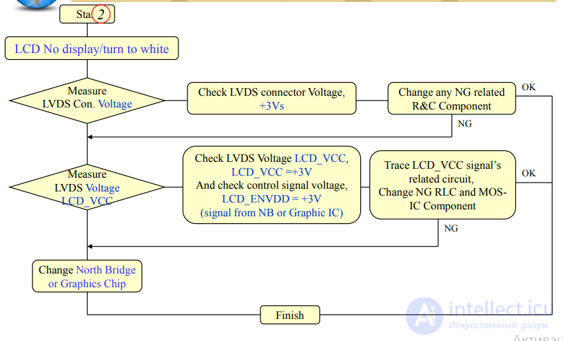
Use Multi-Meter or Oscilloscope to measure Voltage: 1.If problem is LCD too Dark, Check AC_BAT_SYS (on Inverter Con.) signal = 19V 2.If problem is LCD No display or turn white Check LCD_VCC (LVDS Con.) signal = 3.3V
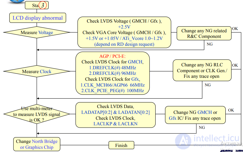
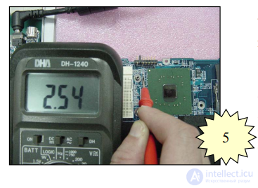 Use Multi-Meter or Oscilloscope to measure Voltage: 3.If problem is LCD display abnormal, 一.Check LVDS voltage = 2.5V 二.Check VGA Core voltage = GMCH: 1.5V or 1.05V Gfx: ATi_Vcore 1.0 ~ 1.2V
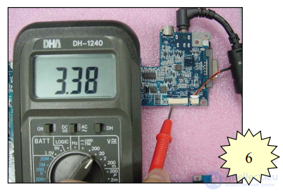
Use Multi-Meter or Oscilloscope to measure Control Signal voltage: 1.If problem is LCD too Dark Check BACK_OFF# = 3.3V Check LCD_ENBACK =3.3V Check LID_RSM# =3.3V Check ADJ_BL =0~3V 2.If problem is LCD No display or turn white Check LCD_ENVDD =3.3V
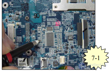
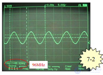
Use Oscilloscope to measure Clock: GMCH platform: DREFCLK(#) = 48MHz (AGP Bus) DREFCLK(#) = 96MHz (PCI-E Bus) Gfx platform: CLK_MCH66/AGP66 = 66MHz (AGP Bus) CLK_PCIE_PEG(#) = 100 MHz (PCI-E Bus)
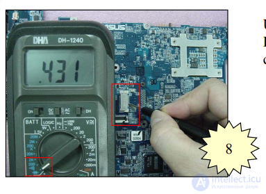
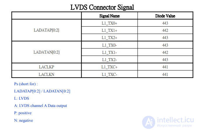
Use multi-meter to measure LVDS Con. Pin signal is correct of Diode value and compare with GOOD M/B. Check LCDS Data signals, LADATAP[0:2] LADATAN[0:2] Check LCDS Clock signals, LACLKP / LACLKN

Comments
To leave a comment
Diagnostics, maintenance and repair of electronic and radio equipment
Terms: Diagnostics, maintenance and repair of electronic and radio equipment