Lecture
A local computer network is a distributed system built on the basis of a local communication network and intended to ensure the physical connectivity of all system components located at a distance not exceeding the maximum for a given technology.

In reality, a typical "average small LAN" consists of three conditional classes of devices:
Modern wired LANs are implemented on the basis of twisted pairs and fiber optic cables.
The main rules of cable laying:
To avoid stretching, the tensile force for 4-pair cables should not exceed 110 N (approximately 12 kg force). As a rule, a force above 250 N leads to irreversible changes in the parameters of the UTP cable;
Diagnostics is commonly understood as measuring performance and monitoring network performance during its operation, without interrupting user experience.
Network diagnostics is, in particular, the measurement of the number of data transmission errors, the degree of utilization (utilization) of its resources, or the response time of the application software.
Testing - This is the process of actively influencing the network in order to test its performance and identify potential opportunities for transmitting network traffic. As a rule, it is carried out in order to check the state of the cable system (quality compliance with the standards), find out the maximum throughput, or estimate the response time of the application software when changing network equipment settings or physical network configuration.
Network troubleshooting hardware.
Conventionally, equipment for diagnostics, troubleshooting and certification of cable systems can be divided into four main groups:
Devices for certification of cable systems - conduct all necessary tests for certification of cable networks, including the definition of attenuation, signal-to-noise, impedance, capacitance and resistance.
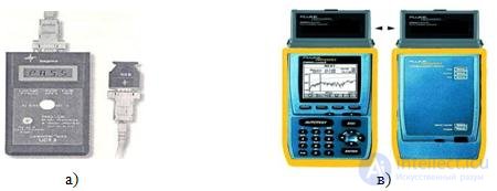
Figure 86 - External devices for testing LAN a) network analyzer, b) cable scanner
Network analyzers are reference measurement tools for diagnostics and certification of cables and cable systems. Network analyzers contain a high-precision frequency generator and a narrowband receiver. By transmitting signals of different frequencies to the transmitting pair and measuring the signal in the receiving pair, it is possible to measure the attenuation in the line and its characteristics.
Cable scanners allow you to determine the length of the cable, damping impedance circuit wiring, electrical noise level and evaluate the results. To determine the location of a cable system malfunction (open circuit, short circuit, etc.), the cable radar method, or Time Domain Reflectry (TDR), is used. The essence of the ego is that the scanner emits a short electrical pulse into the cable and measures the delay time until the return of the reflected signal. The polarity of the reflected pulse determines the nature of the cable damage (short circuit or open circuit). In a properly installed and connected cable, there is no reflected pulse.
Testers (Ohmmeters) - The simplest and cheapest instruments for cable diagnostics. They allow you to determine the continuity of the cable, however, unlike cable scanners, do not indicate where the failure occurred. Check the integrity of the communication lines is performed by sequential “dialing” twisted pairs using an ohmmeter.
Network troubleshooting software.
For troubleshooting, use the built-in testing tools (utilities) of the Windows operating system.
TCP / IP utilities
Checking the connection to the workstation computer using the ping utility.
Ping - diagnostic utility, which checks the connectivity of a remote computer.
Example:
Ping 192.168.0.11 Ping cn.dn.fio.ru
Checking the connection to the workstation's computer using the Pathping utility.
Pathping - |
refined |
ping utility which also |
reflects the route |
|
|
passing |
and |
provides |
packet loss statistics |
on intermediate |
|
routers. |
|
|
|
|
|
Example: |
|
|
|
|
Check the connection with neighboring computers and the server spb.fio.ru.
Pathping 192.168.1.11 Pathping spb.fio.ru
View the server's routing table using the Route utility .
Route - Shows and allows you to change the configuration of the local routing table.
Example:
Route print
View the route to the server and the neighboring workstation using the Tracert utility. Tracert - tracks the route on which the packages are mixed on the way to the point
destination. Example:
tracert sn.dn.fio.ru tracert spb.fio.ru
View current TCP / IP network connection information using the Netstat utility. Netstat - shows information about the connected host and port numbers used.
The Ipconfig utility shows the current TCP / IP configuration on the local computer.
Utility keys:
/ release - frees received from DHCP IP - address. / renew - receives from DHCPNew IP - address.
/ all - shows all the information about TCP / IP configurations. / flushdns - clears the local recognizer cache DNS.
/ regsiterdns - updates address in DHCP and re-registers it in DNS. / displaydns - shows the contents of the recognizer cache DNS. Application examples:
At the workstation, release the received address from the DHCP server.
Ipconfig / release
Check the ip address of the ipconfig / all machine
Get a new address
Ipconfig / renew
View DNS cache content on server
Ipconfig / displaydns
Hostname - shows the locally configured hostname TCP / IP. hostname
FOL testing equipment
Transmission of information via fiber optic cables is booming. At first, fiber optic communications captured the telecommunications industry, supplanted copper cables on the backbone channels, and today they sneak into large local networks and the notorious “last mile” between the provider and the home Ethernet network.
Stabilized Optical Emitters
used to enter into the optical line signal, which will be measured at the output line. Therefore, the signal should be stable and, if possible, monochromatic (have a certain wavelength and a narrow spectrum). The signal power is set by adjusting the current through the emitter.

Figure 87 - Appearance of the stabilized optical emitter
Optical Power Meters 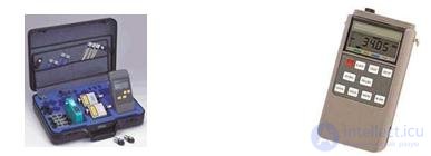
used to measure the optical power of the signal and, paired with a stabilized optical emitter, to measure attenuation in the cable. The main indicator of the quality of an optical power meter is the type of photodiode used in it.
Figure 88 - Appearance of optical power meter
Optical attenuators
They are used to simulate losses in an optical line, which is used for stress testing a line, measuring error rate (BER), calibrating and checking power meters, testing optoelectronic and electro-optical converters, and analyzing the optical budget of a line.
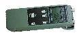
Figure 89 - Optical attenuator appearance
Visual flaw detectors
Such a flaw detector consists of a simple light source for supplying a clearly visible red signal to the cable in continuous or pulsed mode. The flaw detector can be used to visually detect damage to cables and interfaces, detect discontinuities and assess the quality of welds. The light will penetrate to the places where there is a section of increased scattering in the fiber sheath as a result of bending, breaking or poor welding, therefore, to detect it, all that remains is to inspect the cable for the presence of a permanent or flickering red spot.

Comments
To leave a comment
Diagnostics, maintenance and repair of electronic and radio equipment
Terms: Diagnostics, maintenance and repair of electronic and radio equipment