Lecture
Objective: to study the rules and features of the development of electrical structural and functional
nal schemes. Learn how to develop circuits for reduced electrical
schemes on assignment.
In this laboratory workshop there is a relationship between all the works.
The resulting scheme in the first job will be used in all jobs. Save
sources of development work results to the end of the workshop and have them with you on
all stages of work.
Try not to make mistakes! Since it is sometimes possible to detect them late
them stages of work that will require redoing the previous work completely!
Scheme - a design document, which shows in the form of conditional images
or designations of the component parts of the product and the relationship between them. When performing schemes using
use the following terms.
The circuit element is an integral part of the circuit that performs a specific function in
product and can not be divided into parts that have their own purpose (resistive
transformers, diodes, transistors, etc.).
Device - a set of elements representing a single structure (block,
board, cabinet, panel, etc.). A device may not have a specific function in the product.
national appointment.
Functional group - a set of elements that perform in the product
function and not combined into a single structure (the synchronization panel of the main
channel, etc.).
The functional part is an element, a functional group, and also a device; done-
sculpt a specific function (amplifier, filter).
Functional chain - a line, a channel, a path of a certain purpose (a sound channel, video
deokanal, microwave path, etc.).
Interconnection line - straight line segment, indicating the presence of electrical connection
between elements and devices .59
Depending on the elements that make up the product, and the links between them schemes
There are kinematic, electric, hydraulic, pneumatic and combined.
When checking and repairing consumer electronics, electrical and kinematic circuits are used.
The kinematic diagrams show the mechanical parts of the product and their interactions.
Viy (for example, in tape recorders, video recorders, CD players).
Electrical circuits contain electrical elements and their interconnections. They are
are divided into structural, functional, principal, electrical, connections,
connections, location.
Issues of implementation of electrical schematic diagrams in this discipline
we will not give up, because This issue is being studied in other disciplines. Let us only dwell on
which important operational documents and diagrams.
1 Structural diagrams (block diagram)
Structural diagrams define the main functional parts of the product, their purpose
communication and interconnection and are used for general familiarization with the product. On the structural scheme of
It’s not the principle of operation of individual functional parts of the product that is involved, but only the interaction
the interaction between them. Therefore, the component parts of the product are represented in a simplified way as straight lines.
squares of arbitrary shape. It is allowed to use conventional graphics.
graphical construction of the scheme should give the most visual representation of the subsequent
the interaction of functional parts in the product. On the lines of interaction
It is recommended by arrows (in accordance with GOST 2.721-74) - to designate the directions of the processes occurring
walking in the product.
The diagram should indicate the names of the functional parts of the object, which
Rye, as a rule, fit inside the rectangle. Allowed for functional part
indicate the abbreviated or provisional name, which in this case should be
clarified on the schematic field. An example of the design of the structural scheme is shown in Figure 1.1.
It is allowed to put explanatory inscriptions, diagrams, tables, etc. on the scheme;
sequence of processes in time, and also indicate the parameters in x
common points (currents, voltages, etc.), pulse shapes, etc.
With a large number of functional parts allowed to replace items and
designations put serial numbers (from top to bottom and from left to right). In this case, over
the main inscription is placed a table made by the type of the table of the list of elements in
which place the name (if necessary - the type and designation) of the component parts.
Figure 1.2 shows the structural sound-reproducing device. Title block
depicted conditionally. The functional groups in the diagram are highlighted by a dash-dotted line.
Based on the structural scheme, other types of schemes are being developed - functional
nayuyu, principled. In the practice of operation and maintenance, the study of the principle of operation
(diagrams) devices start with structural and functional diagrams
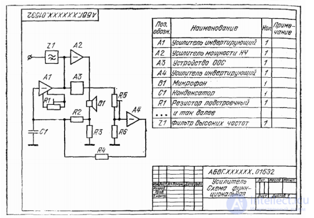
2. Functional diagrams
Functional diagrams clarify certain processes occurring in individual
functional circuits of the product or in the product as a whole. These schemes are used to study
principles of operation of the product, as well as during their adjustment, control, repair.
The functional scheme in comparison with the structural one reveals in more detail the functional
individual elements and devices (Fig. 3) and is intermediate between the principles
general and structural schemes. The functional parts and the connections between them in the image diagram
they are harvested in the form of conventional graphic symbols established by the corresponding State Standards
ESKD Separate functional parts are allowed to represent in the form of rectangles.
Graphical construction of the scheme should give the most visual representation of the sequence
processes, illustrated by the scheme. Elements and devices on the diagram can be
depicted in a combined or spaced way.
For each functional group, device, element must be specified
value, name and type. The name does not indicate if the functional group or
the element is depicted as a conditional graphic designation.
In addition, technical specifications of functional parts may be given.
explanatory inscriptions, diagrams, tables, parameters in characteristic points (values of
current, current waveforms, etc.). Functional schemes are used to
a more complete study of the principle of operation of the apparatus and the repair of household REA.
Functional schemes are used, as a rule, in conjunction with
To this, the alphanumeric designations of the elements and devices on these documents should
be the same. The list of elements in this case for the functional scheme is not developed
melt, as they use the data of the electrical circuit. If functional
The national scheme is developed independently (without a concept), the alphanumeric
digital symbols are assigned to elements and devices according to the general rules;
list of elements in which for each element and device indicate the type and document
(GOST, TU, etc.), on the basis of which they are applied.
It is recommended to indicate the technical characteristics on the functional diagrams.
functional parts (next to graphic symbols or on the free field of the scheme),
charts and tables, parameters in characteristic points.
The number of communication lines on the functional diagram is described in detail
your node corresponds to the concept.
IMPORTANT: the number of blocks on the structural diagram should not exceed 10-15.
When exceeding their number, the study of the work of the scheme becomes more complicated. Decrease number
less than 10 makes it too generalized and does not allow troubleshooting
efficiently.
Recommendations: when developing structural and functional schemes, it is recommended
to use literature:
o Language of radio circuits (Frolov 1988) .djvu

Comments
To leave a comment
Diagnostics, maintenance and repair of electronic and radio equipment
Terms: Diagnostics, maintenance and repair of electronic and radio equipment