Lecture
All installed ata-disk and correctly detected by BIOS? Are they displayed during PC boot?

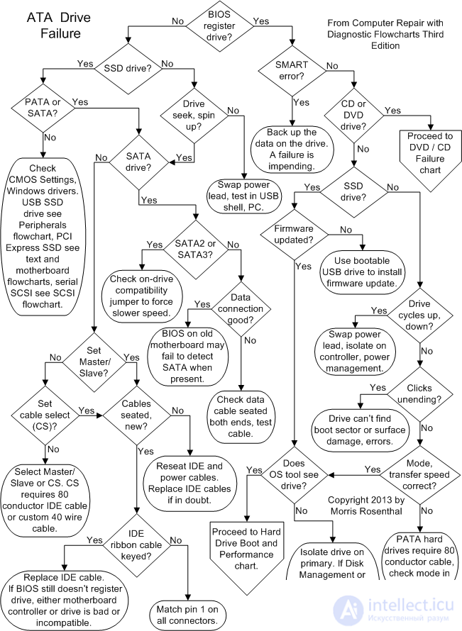
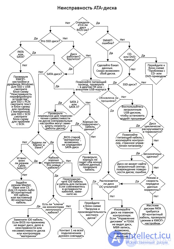
Any modern PC should be able to identify a drive by model number, brand, capacity, and generally transfer mode. Some branded PCs may not show the BIOS startup screen, so you will have to go to CMOS settings to view this data. If at the beginning of the PC boot the screen does not show which key you need to press to enter the BIOS, you need to look for it either in the documentation or on the Internet. Typically, the Del , F1 and keys are used to enter CMOS settings at boot time F2 .

Do you have an SSD (solid-state drive)? Although the BIOS sees ATA SSDs as akin to their mechanical counterparts, they still have several distinctive features, which also affects the resolution of problems that have arisen with them. In particular, they have no motors, no read / write heads on the drive, no spinning discs. Therefore, they do not emit any noise and no longer resist, like gyroscopes, the twisting action. If you failed to update the SSD firmware, turn off the PC completely, unplug the power cord, leave the PC for about an hour, then turn it on / off several times, after each time checking if the SSD is displayed in the BIOS.

Is your SSD equipped with a SATA or PATA (IDE) interface? In terms of handling jumpers (for setting the address) and wires (for power and data transfer), solving problems with SSDs with a PATA / SATA interface is similar to solving problems with magnetic disks. But one of the main problems with SSDs is that they may simply not show up in the BIOS. Of course, an SSD can appear if you turn on / off the PC several times, but I would take this opportunity to make a backup of all important data and return the disk back to the store (if it is still under warranty).
Some SSDs are equipped with a PCIe (PCI Express) interface, but making such a disk bootable can be difficult or even impossible. If you just want to speed up your boot times, a SATA 3 SSD is better. Also, there are USB and SCSI SSDs, as well as even more exotic interfaces that are only used for servers. As a rule, the problem with an SSD is solved in the same way as for any other device with the same interface. That is, if you have a USB SSD, use the USB device branch in the Peripheral Failure Flowchart, and if you have a SCSI SSD, see the SCSI flowchart. If your SSD has a PCIe interface, please reconnect it first and then check for a conflict with the graphics card. Make surethat the version of the PCIe slot on the "motherboard" supports the PCIe version on the SSD, and also that this PCIe slot has all the necessary lanes (x8, x16). Update the manufacturer's drivers and check if a firmware update is needed.

Is the hard drive spinning? I talked about this diagnosis in the Power Supply Failure flowchart, but I'll repeat it here just in case. When the PC turns on, you should hear the motors begin to spin the platters inside the hard drive, as well as the soft clicking sound of the read / write head moving. If I cannot determine if the disks are spinning inside the HDD (even by touching the top cover with my fingers), I take it in my hand and try to twist it slightly. If the disks inside the HDD are spinning, then it will resist a slight spinning motion (like a gyroscope). Do not turn it over too quickly and do not play as you risk damaging the HDD, not to mention not touching the circuit next to the wire, because this could cause a short circuit. Just unplug the drive, plug it back into your PC and continue diagnosing.
One of the reasons you should always use 4 screws on older PATA drives is that you can push too hard on the power connector and just break the socket out of the HDD PCB. This has never happened to me, but I've seen other people do it more than once, so don't overdo it. Before diagnosing the final "death" of the HDD, check it on another PC or using an external USB enclosure.

At this point, the diagnostic tree is divided into newer SATA (Serial ATA) and old PATA (Parallel ATA) drives. When people say "PATA", people also often mean simply "ATA" or "IDE" - these are terms for the same technology. SATA and PATA drives have different connectors for both data and power, so you really have to work hard to connect those drives to the wrong interface. On SATA drives, the power cable is wider than the data cable, and on older PATA and IDE drives, the data cable is a wide ribbon cable, and the power cable is an old school 4-pin Molex connector (it was also used in some of the very first drives with a SATA 1).

Initially, the data transfer rate for the SATA interface (also known as SATA 1) was 150 MB / s. The next generation of SATA 2 already supported 300 MB / s, while the current generation of SATA 3 has already reached 600 MB / s. Since the letter "S" in "SATA" means "serial" (ie "serial data transfer"), then from this figure you can also deduce the bit rate - 1.5 Gb / s for SATA 1, 3 Gb / s for SATA 2 and 6 Gb / s for SATA 3, however, the data transfer rate in hard drives is usually indicated in MB / s, so I used this unit at the very beginning of the paragraph. If you have swapped out an old SATA drive for a newer generation SATA drive, but the BIOS does not recognize it, or the PC is having boot problems, check to see if the drive has a compatibility switch jumper that slows down the interface.so that it works properly with a SATA 1 controller rated for a maximum of 150 MB / sec or a SATA 2 controller rated for a maximum 300 MB / sec.

The SATA interface is practically heaven and earth compared to the old IDE technology, because when working with SATA you have to seriously try to misconnect cables or misplace jumpers. If the drive is supplied with power but is not recognized by the BIOS, then the problem may be a faulty data cable, or that this cable does not fit well in a connector on the drive or "motherboard". If you know for sure that the data cable is working properly (it works fine on another system), try plugging it into a different SATA port on the motherboard. Some motherboards have a separate set of SATA connectors for RAID arrays (see hard disk performance block diagram). If the BIOS of the motherboard supports the AHCI function (from the English "advanced host controller interface"), it must be enabled, otherwise the SATA disk,if it works, it will just emulate an IDE disk. If Windows is already installed, see the "Just switched to AHCI?" For more information, see the Hard Disk Loading and Performance flowchart.

Whenever two old IDE drives share the same cable, the PC should be able to give them a sharing command. This can be done using the jumpers on the drives, one drive has a jumper on the Master, and the other - on the Slave, or you can do it using the Cable Select function. The Master / Slave settings are set using jumpers, which are usually found on the back of the drive between the power socket and the IDE connector. The text for these pins is usually abbreviated to one letter - “M” for “Master” and “S” for “Slave”. Some older drives have pins for Single mode (and verbose text) for situations where this is the only drive connected to the ribbon cable. If you are dealing with a "motherboard" released after the advent of SATA (they always had the main and secondary IDE interfaces),then you don't need to connect two drives to the same cable. The boot disk must always be Master connected to the main IDE interface. If a CD or DVD drive, or another IDE drive is connected to the same cable, this device should always be set to Slave.

Most later PATA drives support Cable Select (CS), which means that pin 28 of the cable will determine which drive is Master and which is Slave. New motherboards and drives are shipped with 80-pin ribbon cables that support Cable Select and have several colored connectors: IDE connector for motherboard - blue, IDE connector for Slave device (middle cable connector) - gray, connector for Master devices are black. Cable Select is also supported by custom 40-pin ribbon cables and older drives found in many branded PCs. If you decide not to make one disk Master and the other Slave, then jumpers on both disks must be set to Cable Select (CS).

If the BIOS still does not recognize the drives well, check that the power cable is well seated in the power connector on the drive. If not, insert properly, and this will require a little force. Strictly speaking, all ribbon cable connectors must be properly connected to the IDE ports of both drives and the motherboard or expansion card (if you are using a RAID expansion card). In this case, the most common cause of the problem is that you could accidentally damage a connector if you did some work in the case before. Try a new ribbon cable. Most often, it is the connectors that break in the cables - if the latch is damaged, then the connection between the contacts is obviously broken. In addition, the connectors are not soldered to the wires: their connection is made mechanically using V-shaped contacts,squeezed through the plastic and into the wires.

Are there so-called "keys" on the ribbon cable connectors, as well as on the IDE ports of the HDD and motherboard? On the connector, the key is made in the form of a protrusion, and on IDE ports - in the form of a slot. When connected, the protrusion falls into the slot so that the user knows exactly which side to connect the cable to the port. Locate pin 1 location on all connectors and ports. On IDE drives, pin 1 is usually located near the power socket, but this is not always the case. If the connector on the "motherboard" has neither a key nor a rectangular frame, there is a possibility that you will stick the cable upside down or connect only one row of pins at all. The location of pin 1 on the "motherboard" is usually marked with an arrow, a dot, a white square or something else - this is necessary so that you understand that one edge of the connector is different from the other.If the motherboard does not recognize the drives connected to it, even if they are connected with new cables, and if those drives are spinning anyway, then the problem is either with the IDE controller or with all of your drives. If you have used only the main IDE controller before, try the secondary one, but if this does not help, then you will have to either buy an IDE adapter or change the "motherboard".

SMART is one of those cute acronyms that PC users have in their worst dreams. It stands for "self-monitoring, analysis and reporting technology" (ie "technology of self-monitoring, analysis and reporting"), and this, in essence, a harbinger of fate, but to believe it or not is, of course, solely on your discretion. The SMART system includes 87 different messages: from the spinning time of disks (from rest to operating speed) and the frequency of software read / write errors to disk temperature and vibration. For this reason, hard drive manufacturers do not always implement SMART in the same way and completely.
Not all motherboards support SMART messages, and they can be enabled / disabled using CMOS settings if desired. In addition, the OS supports SMART rather superficially, but on the net you can find many free monitoring utilities that work on any version of Windows and are able to read SMART data from a disk. If you receive a message from the OS or BIOS of the "motherboard" about an imminent disk failure, I advise you to make a backup of the data, and then, if funds permit, replace this disk as soon as possible. Just be careful when looking for monitoring utilities and do not download any “malware” that pretends to be a program for issuing SMART alerts!

All problems with ATA devices not recognized by the BIOS (be it hard drives, CD drives, DVD drives, tape drives, etc.) are solved in the same way. If the BIOS recognizes the attached ATA drive correctly and you have a problem with your CD or DVD drive, go to the “CD or DVD drive problem” flowchart.

Is your drive an SSD (solid state drive)? Here, again, the diagnostic paths diverge because HDD (mechanical disk) and SSD problems are handled differently. SSDs cannot go into a continuous spinning / braking cycle because they simply do not have elements inside that could spin. Mechanical hard drives almost never require software updates, largely because their operating parameters are fixed and almost nothing can be changed.

The plates inside the disc either spin or stop spinning, and is this always the case? Try connecting a different power cable (perhaps you have a spare one, or you can use a similar cable from another PC). If it's an old IDE drive, try unplugging all other devices from the ribbon cable and leaving only that IDE drive on it (even if that means temporarily leaving your PC without another drive). If all else fails, try unplugging the data cable to make sure the drive is not receiving some weird shutdown signal from a faulty ATA interface or some weird power management circuitry. If the spin-up / slowdown cycle hasn't stopped, your disk is most likely done. But before throwing it out with a free soul,however, just in case, test it on another PC or with an external USB enclosure.
If you are dealing with an old disk whose disks are spinning, but the read / write head does not move, then this is most likely a hardware problem. Here, in principle, you can already send the disk to a data recovery specialist, but in the end, you can try a couple more methods. First, take a screwdriver and lightly press down on the disc cover, but not in the place where the plates are spinning - this can cause the stuck head to start moving again. Secondly, you can use another rather controversial method: put the disk in the refrigerator at night (after packing it in two freezer bags and putting a desiccant inside) - this can give you temporary access to the disk data until problems begin to pester him again with overheating or condensation concentration. But before these last attempts, make a data backup,because two times these methods usually don't work.

Does the drive make soft clicking sounds while refusing to start? These endless soft clicks are an indication that the read / write head is jerking back and forth trying to read data from the platter. The reason may be a damaged magnetic coating, tracking errors, various mechanical failures. I have heard from some data recovery specialists that they sometimes bring hard drives, whose screws holding the cover are tightened with uneven force (due to the fact that users tried to disassemble them themselves), which ultimately leads to clicks. The site https://intellect.icu says about it. If you have a good quality torque screwdriver, I advise you to set it to the smallest torque first, and use it to check if the screws are evenly tightened on the disc. Restart your PC several times,and if it boots, make a backup of the data, run CHKDSK or ScanDisk and try downloading a free utility that will check if the disk is sending any SMART messages.
If you cannot boot, but the data you need remains on the disk, it always makes sense to connect this disk to another PC as a second (non-bootable) disk, or connect it to an external USB enclosure and connect to a laptop. If the problem was in the boot sector and the disk index is intact, you will be able to read all of your data. If it doesn't work, you can try a third-party data recovery software or, if the situation is really critical, give the disk to a data recovery specialist. If you are not afraid of losing all the data on the disk, then you can format it and then reinstall the operating system, but problems with mechanical search usually say that your disk will soon glue its fins.

Does the BIOS correctly report the transfer mode (like UDMA / 100 or ATA / 66) for the old PATA disk? UDMA can be enabled in CMOS settings or set to "Auto" to enable higher data rates. There should never be a PIO option in the HDD settings. IDE hard drives made after around 1995 require an 80-pin ribbon cable (at least for high speed data transfers). In CMOS settings, there may be a manual switch that allows you to select a higher baud rate, but this can be achieved with automatic settings. Also try to isolate the disk i.e. make it the only device connected to the main controller. If you added a new HDD to an old PC, it may happen thatthat the BIOS and motherboard simply won't be able to support higher speeds even with a new cable. And I am skeptical about flashing the BIOS in order to increase the data transfer speed, even if the motherboard manufacturer has released a new firmware version.

Is your SSD software updated? Unlike mechanical HDDs, whose operating parameters are fixed, SSDs sometimes perform better after installing a new firmware. But I advise you not to update if it is not recommended by the SSD manufacturer. The SSD firmware has a relatively heavy burden of managing the tasks that the drive must perform independently of the PC, especially wear leveling and other tasks to extend the lifespan of the SSD. Firmware update may be necessary after automatic Windows update. after that, compatibility issues start to arise between Windows and SSD. In addition, a firmware update can be useful to speed up the performance of some resource-intensive program.

Can you access the disk and see its partitions using any version of Windows Disk Management or FDISK? If the partitioning information is intact, the problem is often malware or a corrupted OS, rather than a malfunctioning magnetic and electronic disk. If the disk works, but makes a very loud noise, I advise you to make backups every day, but this can take years. If the drive is very hot, try relocating it inside the PC for better airflow, or adding a new fan to the front of the case.
If Windows boots from this disk, make sure you have the latest drivers for all motherboard devices, including the integrated disk controller. If it is an additional or external drive, use Disk Management to check the partitioning of the disk: in the Status column, the partitions should read Good, they should not have a Raw file system, and their memory should be allocated. If you have any other problem with your hard drive, go to the Hard Drive Loading and Performance flowchart.
Parallel ATA, PATA - Parallel ATA, which is also known as IDE (Integrated Drive Electronics), was the most widespread until recently.
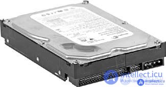
Figure: 9.2. ATA hard disk drive
Modern MPs often have only one ATA interface already installed. There are less and less two or even four interfaces for IDE devices. If there are two interfaces on the MP, then one of them is the main - primary, or primary, - primary ATA, and the second - additional, secondary - secondary ATA. They function the same, their electrical circuits are identical. But the first one has priority. Therefore, the master device (drive) - Master is connected to the primary channel. Most often, an HDD is connected to it, on which the operating system is installed, and a CD drive is connected to the secondary channel.

One or two devices can be connected to one channel. The ATA has its own internal controller. Only the controller of one ATA device (Master) can be activated on one interface. If a second device is connected to the same interface, then it must be set to the passive position (Slave). So, if there are two ATA connectors on the MP, then the device that is connected to the MP can be installed in one of four positions: Primary - Master, Primary - Slave, Secondary - Master, Secondary - Slave.
The devices have jumpers that can be used to set the appropriate configuration. The drive usually has a jumper layout. It is not always possible to remove the jumper with your fingers; a sharp object, a screwdriver, tweezers are suitable for these purposes.
If there is one device on one channel or you want to define this device as Master, then set the jumper to the appropriate position.
If you connect an additional device to a channel where the drive is already installed in the Master (MS) position, then set it as Slave (SL).
Regardless of whether the device is connected to one of the cable connectors - in the middle or at the end, when the jumper is installed, it will work exactly in accordance with the position in which the jumper is installed.
For configuring devices, a cable select option is also provided, which can be referred to as CS, CSEL. In this case, depending on how the device is connected to the cable, it turns out to be a master or a slave.
There are two types of ATA interface data transmission mode. These are PIO Mode (Programmed I / O Mode) and DMA (Direct Memory Access Mode) mode. The first mode is much slower than the second because it uses processor resources to transfer data. The second mode is bypassed without using the CPU. If one device in a channel operates in PIO Mode, then the second device in the same channel must operate in the same mode, which creates a heavy load on the CPU. Modern drives support DMA and can be configured to operate in PIO mode.
There are special cables for ATA connection - ribbon cables with three connectors.
The connectors that are located close are designed for attaching drives, and the far connector connects to the MP.
The ATA hard drive uses a 40-wire cable and an 80-wire (Ultra DMA) cable.
On a 40-wire data cable, the colored bar represents the first pin.
When the drive is connected to the middle connector, it becomes Master, and the disk connected to the outer connector becomes Slave. This cable used to be connected to CD drives.
The 80-wire cable has an additional 40 wires installed for grounding. Each of them corresponds to one of the 40 signal wires of a standard ATA loop.
This cable configures drives differently. The drive connected to the middle of the cable is Slave, and the drive connected to the far connector is Master.
The main hard disk, on which the operating system will be installed, is designated as Master, it must connect to the primary MP interface.
Try not to connect a hard disk drive and a CD-writer (DVD or CD) to the same cable.
If you are installing a hard disk drive and a CD-ROM drive on the same cable, you must install the hard disk as Master and the CD-ROM drive as Slave.
When connecting different devices on the same cable, the faster device starts to work at the level of the slow device. For example, you connected two DMA hard drives - one faster, one slower, then the faster one will run at the slower speed. If you "hang" one device with DMA support on one loop, and the other has only PIO mode, then the DMA disk will switch to PIO mode.
This cable usually connects devices operating in UltraATA-66, Ultra ATA-100, Ultra ATA-133 modes (UDMA Mode 4, UDMA Mode 5, UDMA Mode 6).
In such a cable, usually the blue connector is connected to the MP, the black connector (extreme) is designed to connect the Master device. When using this cable, do not connect the master drive to the middle connector, even if it is the only device on this cable, it can only be connected to the end of the cable. The gray connector is in the middle and is intended for connecting a Slave drive.
If the drives have jumpers set to CableSelect mode and you rearrange the cable - install 80-wire instead of 40-wire, then the devices will exchange statuses: Master becomes Slave, and vice versa.

Figure: 9.3. 80-wire UltraDMA ATA cable
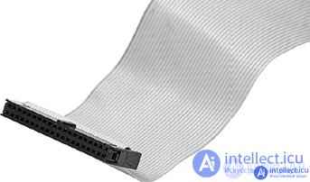
Figure: 9.4. 40-wire standard ATA cable
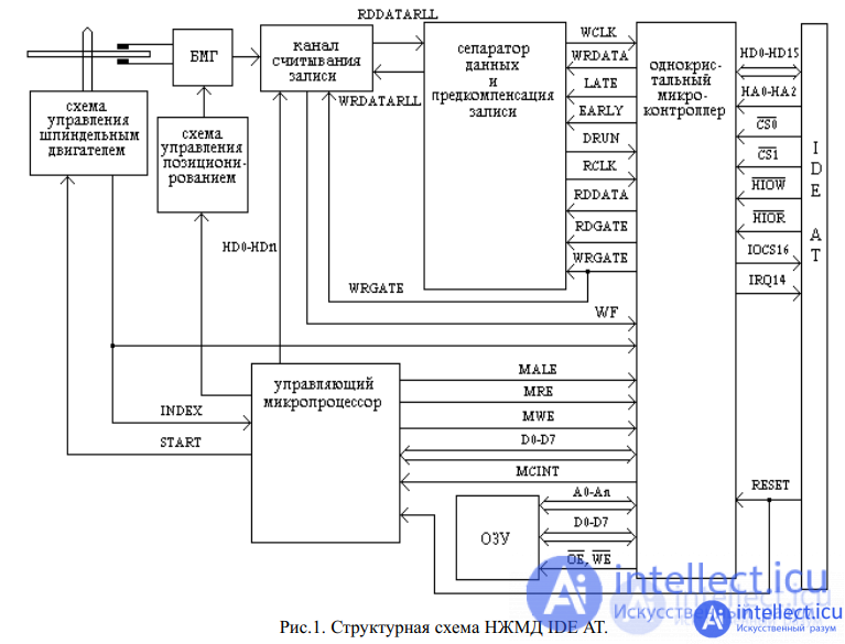
The board, which is connected between the system bus of the computer and the hard disk drive, acts as a
decoder of the base addresses of the controller and a generator of interface signals. The site https://intellect.icu says about it. In IDE AT standard,
two HDDs can be connected, MASTER and SLAVE. Switching the drive mode is performed by a
jumper, with the first logical disk being MASTER. The IDE AT interface only supports
software I / O using the hardware interrupt IRQ14. Physically, the interface is implemented
as a flat 40-pin cable with a recommended length of 50 cm. The distribution of signals by contacts is
shown in Table 2.
table 2
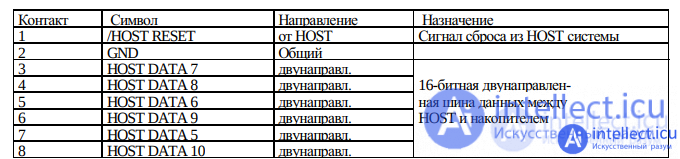

Note. The names of some signals in different technical documentation may differ.
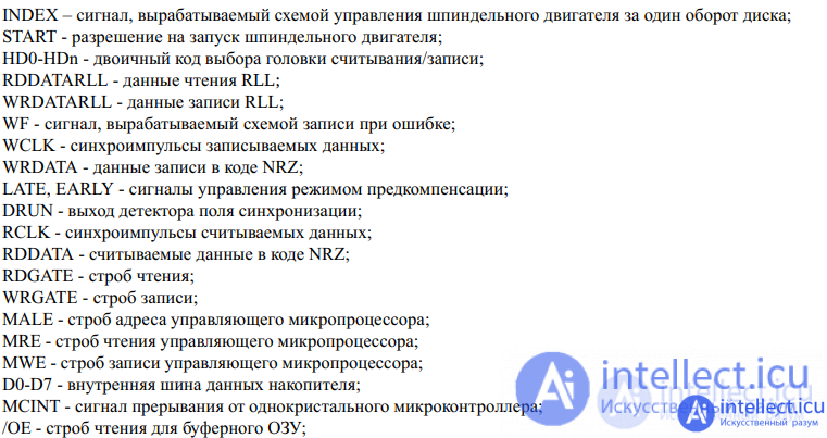
All signals of the IDE AT interface can be divided into groups.
Buffered standard signals of the ISA bus of the PC PC AT:
/ HOST RESET (on the ISA bus it has a non-inverse value);
HOST DATA 0-15;
/ HOST IOR;
/ HOST IOW;
IO CH RDY;
HOST ALE;
HOST IRQ14;
/ HOST IO CS16;
HOST ADR0;
HOST ADR1;
HOST ADR2;
DMARQ;
DMACK.
Additional signals to address the job file:
HOST CS0;
HOST CS1.
Signals of interaction between HDD MASTER / SLAVE:
PDIAG;
HOST SLV / ACT.
Control signal transmitters - TTL circuits must provide a current:
IoL not less than 12 mA,
IoH - 400 uA
Currently, this interface is very actively replaced by the SATA interface.
IDE AT HDD malfunctions can be divided into the following groups:
Malfunctions with initial initialization lead, as a rule, to the complete inoperability of the
drive. In a HDD with such a malfunction, very often even the spindle motor does not start (
due to the fact that the control microprocessor does not give permission to start) or starts, then
stops and starts again, etc., but in all cases the HDD does not generate a 50H code in status register
(see status register bits). The main reasons why the drive's control microprocessor can
not perform initial initialization:
In order to check how the microprocessor performs the initial initialization, it is necessary to have a
listing of the control microprogram, then you can check exactly where and for what reason the
HDD is stopped or reset. As a rule, the drive algorithm is unknown and, moreover, it
is a KNOW-HOW of the HDD manufacturer, and the algorithms of operation of various models (even of the same
manufacturer) are very different. For all these reasons, this approach to troubleshooting
initial initialization is not practical. The following troubleshooting technique is proposed.
It is necessary to check the supply voltages on the control microprocessor single-chip
microcontroller, excitation of a quartz resonator connected to the control microprocessor,
or the arrival of clock pulses if an external generator is used, as well as all synchronization circuits of the
drive. Next, you need to check the hard drive reset circuit. To do this, close and open contacts
1 and 2 of the drive interface connector and the oscilloscope observe the passage of the "RESET" signal to the
control microprocessor and the single-chip microcontroller. As a control microprocessor in IDE AT HDDs, as a rule, 8-bit single-chip microcomputers are used:
Zilog Z8, Motorola 68HC11, intel 8051 family, or 16-bit: Motorola 68HC16, Intel family
80196. If clock pulses come to the control microprocessor (or a quartz crystal is excited, they must be controlled immediately after the "reset" signal has passed, otherwise you may not see the presence of pulses due to the microprocessor freezing. on the ALE pin, the drive's control microprocessor is most likely faulty. Do not "bite out" such a microprocessor, you must use a soldering station to dismantle chips in PLCC and QFP cases so that you can use it in case of incorrect diagnostics.
resonator connected to the microprocessor is ) and the reset circuit is working, then the microprocessor must execute the control program , as evidenced by pulses at the terminals ALE, / RD, / WR, and
drive microprocessor, it is necessary to pay attention to the firmware code (firmware version) and
replace the microprocessor with the same firmware code as it was, if it is not known for sure that read control programs from the disk due to a malfunction in the HDA or in the read channel.
other firmware version is compatible. If the crystal resonator of the microprocessor is excited and
there are pulses at the ALE, / RD, / WR pins, then most likely the spindle motor of the HDD is
rotating. In such a situation, very often the drive does not go into readiness due to the fact that it cannot. This is especially often manifested in drives with a solenoid motor. To check the HDA, you need to use a serviceable board from a similar drive, you just need to remember motor is not given, then most likely the microprocessor expects some kind of
on the compatibility of the microprocessor firmware and operating programs stored on the magnetic disk. If
there are pulses at the microprocessor pins ALE, / WR, / RD, and enable the start of the spindle control or ready signal. Without a schematic diagram of a hard drive and without knowing the drive operation algorithm, you can check the internal readiness signals of a hard drive as follows. It is necessary to put a jumper on pins 1 and 2 of the drive's interface connector (simulate the / RESET signal), compare the logic levels at the pins of the control microprocessor and the single-chip microcontroller with the logic levels taken from a similar working hard disk drive . The identified
mismatch will help in determining the malfunction. If the drive starts reading the service
information, which can be verified by the characteristic sound of the positioning system, then most
likely the malfunction is not related to the initial initialization. It is convenient to observe the state of the drive drive parameters are entered from the database. To check initialization, you can use the command
on the LEDs of the status register, which is constantly updated even if no commands are sent to the
IDE AT hard drive. When diagnosing a drive that fails initial initialization, “RESET” is in the controller check mode. This command performs hard disk drive reset, initialization and recalibration. When executing the command, it is necessary to observe the HDD status register .
The technique for finding the malfunction of the spindle motor control circuit is considered in.
The criteria for starting a spindle motor are: supply voltage on the control chip,
reference clock frequency and start enable signal. If all these conditions are met, and the
spindle motor does not start, then either the control chip or the spindle
motor is faulty . The operability of the spindle motor can be checked using a good
control board . It is necessary to control the reference clock frequency and the start enable signal immediately
after turning on the power for 2 - 4 seconds. This is due to the fact that in order to avoid burnout of the windings
spindle motor, the control microcircuit is disabled if the
index pulses do not come to the control microprocessor for several seconds . The spindle motor may start
to rev and stop. This happens most often due to the fact that the control microprocessor
monitors the rotation speed of the magnetic disks by measuring the pulse repetition rate
index, and if for a certain period of time the rotation speed of the magnetic disks has not reached the
nominal value, then the control microprocessor removes the permission to start the spindle
motor or prohibits the reference clock frequency. It is quite difficult to find a circuit malfunction
spindle motor control in hard in which as feedback instead of hall sensors CFA, CFS, Western Dig. Caviar, etc.). In such hard disk drives, the spindle motor is pre-
the built-in service information is used (Seagate ST3144A, ST3290A, ST3660A, Conner CP-3xxx, spins up by the control circuit, up to a certain nominal speed, so that the magnetic heads take off and can read servo labels, after which the rotation stabilizes (this is especially clearly visible when turning on the power Conner drive in technological mode) .Therefore, due to the destruction of service information, a malfunction of the HDA or the servo channel of reading, the spindle motor can start and stop.
If the positioning system malfunctions in the IDE AT hard drive, both random
failures (reading errors appearing on different cylinders) and complete inoperability of the drive
due to the hard drive cannot read service information may appear. To check the
positioning system , it is necessary to perform tests: format check and random read. The
format check test will check the operation of the positioning control circuit, and the random read
test will check the correctness of the positioning mechanics. In HDDs with a stepper motor with conventional phase
control, a control circuit malfunction is expressed in a cyclic appearance of an error on the cylinders in
multiples of the stepper motor cycle. For example, ST157A with a stepper motor cycle of 20 errors
appear on cylinders: 8,9,11,28,29,31,48,49,51, etc. In
case of such a malfunction, it is necessary in the "CHECK DRIVE" mode , using the step-by-step movement commands [STEP +] and [STEP-], to
position on these cylinders and observe the analog signal of the read data at the
control point of the read channel with an oscilloscope . If the signal on these cylinders is blurred, and on the rest it is
clear, then the stepper motor control microcircuit is most likely faulty. When diagnosing a
fault, you must also use the static voltage test on the stepper motor in
accordance with its cycle. In HDD with a stepper motor with a pulse-width phase
control, a malfunction of the control circuit is expressed in a very slow reading of data from the disk, or in the
appearance of numerous random errors due to the fact that the tuning system does not work correctly.
To check the positioning system with a pulse-width phase control of a stepper
motor, it is necessary to
move the positioner from cylinder to cylinder in the "CHECK STORAGE" mode using the [STEP +], [STEP-] commands . In this case, it is necessary to monitor the
readout analog signal at the control point of the read channel. With a working
positioning system , the stepper motor shaft will rotate evenly, and a
clear, not blurry signal will be observed on the oscilloscope screen . If, when executing the [STEP +] or [STEP-] command, the signal
reading is blurry or very slowly turning into clear, then the positioning system is magnetic disks is , to check the operability of the read servo channel and the ADC circuit, the mismatch circuit
defective. In this case, it is necessary to make sure that the service information located on the SHIFU generator is in good working order (see Fig. 2). To check the serviceability of the service information, it is best to use a control board removed from a similar working drive, while the entire mechanical part of the positioning system is automatically checked . To check the read servo channel, it is necessary to control the passage of the read data with an oscilloscope to the input of the ADC circuit. The method for checking the ADC circuit, design of devices. In a HDD with a solenoid drive, the mechanical part of the positioning system is very reliable
mismatch circuits and generator PFCS depends on the specific circuit solution of these functional because of its simplicity and almost all faults are associated with the electronics of the control circuit. The only malfunction in the HDA, which is not so rare, is a break in the solenoid coil. A break usually occurs at the place of soldering to a flexible cable and it is quite easy to fix it. Such a malfunction can be easily detected by dialing an ohmmeter on the connector without opening the HDA. Solenoid resistance is about 30 ohms. As for the repair of the control circuit, we can advise the method of replacing the servo controller microcircuit with a known good one, removed from another drive. For this, it is better to use a soldering station for
housings PLCC and QFP, or you can adapt a heat gun for soldering linoleum with a
hot air temperature of 200 - 300 ° C.
Failure of the IDE AT hard drive read / convert data channel may lead to
random read errors, lack of reading, or complete inoperability of the drive due to
the fact that the hard drive cannot read service information from the disk. As a rule, these are IDNF errors, and the
appearance of AMNF, UNC, CORR errors or the appearance of at least one track without errors indicates
that the data conversion channel is most likely good and the error should be looked for in the read channel, “broken”
surfaces or a partially destroyed low-level format. To check the channel for reading / converting
data, it is necessary to perform the "CHECK FORMAT" test. If during test execution the number of errors
exceeds 50, the test can be aborted. In the listing of test results, each error must be
identified in accordance with its code. It should also be remembered that for most IDE AT hard drives, the
physical organization of the disk space does not correspond to the logical one due to the translation mode.
Therefore, the appearance of errors on all surfaces after a certain number of cylinders is possible due to the
lack of reading on one specific physical surface. Finding a fault in the reading channel is
performed in the "CHECK STORAGE" mode. In this mode, when the [HEAD] heads are switched, the tester
sends the 41H - Verify command to the drive (checking the track format), while information about the appearing
errors is displayed on the LEDs of the status register and error register. In this mode, they check up to the separator microcircuit, while you can use the method for checking the read channel of the ST506 / 412 drive . To check the microcircuit of the BMG switch and the BMG itself, you must turn off the broadcast mode. To do this, in the "SELECT DRIVE TYPE" menu, in the User Type, it is necessary to specify the physical parameters of the first zone of the tested drive, then execute the command "Reset NMD" from the " CONTROLLER CHECK" menu . In this case, on the zero logical cylinder, the logical numbers of sectors and heads will correspond to the physical ones. In case of faults in the read channel, it makes no sense to execute the write command
operability of the switch microcircuit and the data read processor, the passage of the read data
case of [WRITE] , because before writing data, the IDE AT hard
disk drive checks the identification field and, if it is not found, the write will not be performed, and an IDNF error will be generated. If
reading data is present at the input of the separator microcircuit when all heads are switched, then most likely the
IDE AT HDD read channel is working properly. The next step is to check the data conversion channel,
which includes a separator microcircuit and a single-chip microcontroller. The switching circuit of the
separator microcircuit and a single-chip microcontroller is shown in Fig. 20.
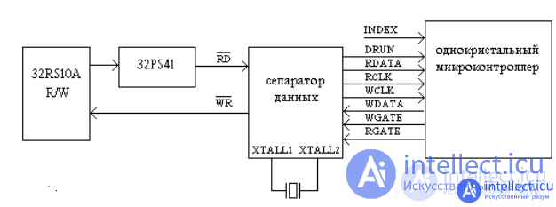
Fig. 20. Scheme for switching on a separator and a single-chip microcontroller.
A malfunction of the data conversion channel is indicated by the appearance of an IDNF error on all surfaces and all cylinders. Testing the separator microcircuit begins with measuring the supply voltages
and the clock frequency of the reference generator. Typically the reference frequency for the 2.7 RLL code is 15 MHz.
Then, in the "CONTROLLER CHECK" mode, give the "READ SECTOR IN A
CYCLE" command. For tester requests, you must specify the number of the head, cylinder and sector. You just need to
make sure that the low-level format on this track is working (it is best to do this with a
working control board). If the format of the lower level is correct, the
control signal diagram shown in Fig. 21 should be observed .
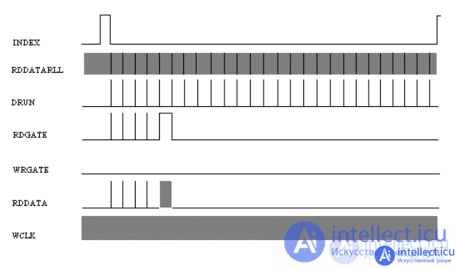
Fig. 21. Reading (the 5th sector is read).
It must be remembered that this diagram is generalized and only shows the method for checking the separator
and the single-chip microcontroller. The actual diagram depends on the microcircuits used and the
drive operation algorithm (in particular, the sector reading algorithm) and can be taken from a similar working
drive. When checking, a two-beam or two-channel oscilloscope is required, which must be
synchronized from the INDEX pulses entering the single-chip microcontroller. One
channel "becomes" on the incoming pulses index, the other one checks the incoming control signals
and data signals. The sweep is chosen such that one or half of the pulse period fits on the screen
index.
Failure of the write channel, as a rule, makes it impossible to write to the
IDE AT hard disk drive, although reading from the drive is normal. It should be recalled that when recording, the drive
pre-reads the track format, compares the read identification field with the specified one, and if they
match, only then the data is directly written to the sector, Fig. 22.
The main faults in the recording channel are as follows:
In these cases, the WRFT bit of the status register is usually set. You can check the recording channel in
the "CHECK DRIVE" mode. While in this mode, it is necessary to control the readout
data by the oscilloscope at the control point of the readout channel. When switching heads with the [Gol] command,
it is necessary to make sure that data is read over all surfaces and no read errors are observed. After
that, you need to record the track with any selected code. The signal on the oscilloscope screen should
change, if necessary, you can re-record with a different code. This operation must be
performed on all heads. Please note that the selected recording code is converted to HDD
into one of the numerous write codes: 1.7RLL, 1.8RLL, 2.7RLL, 2.8RLL, ARLL, etc. used in this
drive model, therefore the same write code may have a different look on different models HDD
IDE AT.
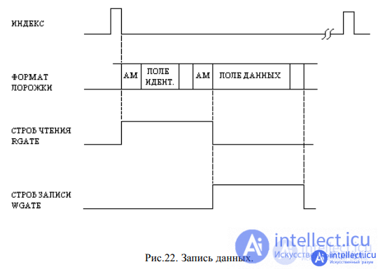
Fig. 22. Data recording.
If the data is not recorded, then it is necessary to check the control signals generated by the microprocessor
and single-chip microcontroller. To do this, in the "CONTROLLER CHECK" mode,
select the "RECORD SECTOR IN A CYCLE" command, enter the number of the cylinder, head and sector. Checking is
carried out in the same way as reading. A generalized diagram of control signals when recording a sector is shown
in Fig. 23.
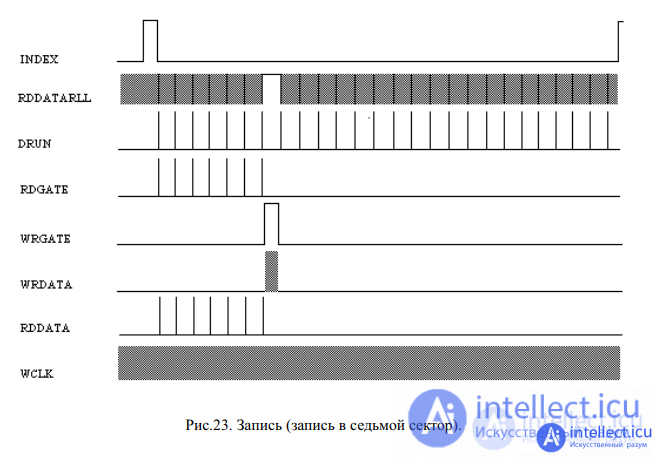
Fig. 23. Write (write to the seventh sector).
A malfunction of the precompensation circuit, as a rule, leads to numerous read errors
appearing on the senior cylinders. It should be remembered that
precompensation affects the data being written and errors will occur when reading such written data with a healthy read channel
. If reading errors appear on the senior cylinders on the IDE AT
hard disk drive, try to format the HDA of the inoperative drive using a working control board removed from a similar hard disk drive. If, after that, when reading the "native" control board, the errors on the senior
cylinders disappear, then the precompensation circuit is most likely faulty. In modern HDD IDE AT
a single-chip microcontroller, which encodes the data being written, generates
the EARLY and LATE signals (early and late), Fig. 15, necessary for the operation of the precompensation circuit in Fig. 12.
As a rule, these signals are generated continuously, but the permission for data precompensation is given from the
control microprocessor from approximately the middle of each zone. The inclusion of precompensation
must be checked when performing the surface erasure test [Erase] in the "DRIVE CHECK" mode
. It should be noted that for some IDE AT hard drives, write precompensation is
enabled from the zero cylinder itself.
Service information for different HDD models is strictly individual (see section 1.3); it may
differ for the same HDD model of different production series. If the service information is lost,
almost all IDE AT HDD models become unusable, although their electronics and mechanics are in
good order. Moreover, a drive that has lost its service information cannot even be diagnosed
in a normal non-technological mode of operation (for example, all Seagate models give an ABRT error). For
reliability, service information is duplicated in several places in the technological zone of the drive.
The destruction of service information and the appearance of defects usually occurs for the following
reasons:
The need to restore service information and hide defects arises in most
cases of repair work.
To restore service information of IDE AT drives, you must have special
hardware and software. Thus, the restoration of the lower-level format, operating programs,
the configuration table, the disk passport and the hiding of defective sectors (except for the assign mode) is
carried out in the technological mode of the drive, when turned on, the
entire disk space of the drive becomes available . The technological mode is
switched on differently for different drive models and occurs either by a command from the interface or using a special technological connector.
For some drives, the technological mode is turned on when a
special ROM is installed in the socket instead of the main one. After turning on the technological mode of the drive
, a special set of commands becomes available, with the help of which the
service information is recorded or restored . In addition, in the technological mode of operation, many drive models allow
for more stringent diagnostics, for example, when checking the surface (Media analys), the drive
narrows its detection window for more stringent testing of magnetic surfaces. To
restore service information and diagnose drives in technological mode, the
complex "RS-3000" includes additional adapters and utilities (see the description of utilities of the complex "RS-3000").
It is
practically impossible to prescribe the service information of drives with a solenoid drive of magnetic heads in the conditions of service companies, since it is written at the manufacturing plants directly
onto magnetic disks in the assembled HDA using special precision installations - servowriters
(SERVOWRITER). To record service information, a special technological window is used in the
HDA. Typically, servowriters write service information to only one
drive family . These instruments use precision mechanics, laser travel distance meters and
etc. It is possible to repair drives with corrupted service information such as Embedded by
excluding or replacing BAD sectors with spare ones, excluding or replacing BAD tracks, excluding the
entire defective surface from operation. The listed operations are individual for each family of
drives and are performed in its technological mode of operation (see the description of the utilities of the PC-3000 complex).
Recovery of servo information in drives with pulse-width phase control of a stepper
motor is carried out either by command in the technological mode as in KL3120 drives from KALOK
and DX3120 from Daeyoung, or, as in drives with a solenoid drive, using
servowriters. To restore the SI drives of the WD93044A family of Western Digital and ST351A / X
of Seagate, ACE Laboratory offers its developments the SW-WD9X and SW-ST351 servowriters.
The IDE AT hard disk drive uses a positioning system with both a stepper motor and a solenoid drive (voice coil), and recently the positioning system with a solenoid drive has almost completely replaced the positioning system with a stepper motor. This is primarily due to such a characteristic of the hard disk drive as the average access time. The second reason is the ever increasing recording density due to an increase in the number of cylinders on the working surface and, as a consequence, a decrease in the distance between two adjacent tracks. In modern hard disk drives, balanced rotary positioning systems are used, which are more reliable and take up significantly less space compared to linear ones used on the first models of hard disk drives.In drives with a solinoid motor, two types of SI are used to accommodate service information (necessary for positioning magnetic heads):
- SI on a separate (dedicated) surface (dedicated surfase) ST1144A, ST3144A, ST3283A, ST3655A, LXT340A, MXT540A;
- Embedded CI (embedded).
The latter, in turn, is subdivided into SI, located between the sectors and the SI, built into the format. The first includes models WDAC2120A, WDAC2200A, etc., of the Caviar arhitecture-0 family; Early models of the CP-3xxx family, CFA and CFS from Conner and others. In such models, the number of marks on the track exactly corresponds to the number of drive sectors and they are located strictly between sectors. Moreover, the number of servo marks on the track changes in accordance with the zone distribution.
Technical description and general principles of HDD repair IDE (ATA) modern drives use SI built into the. At the same time, the number of servo tags on all tracks is the same and equal, as, for example, in the ST3660A model - 60. In such drives, the format is not tied to the servo tags and the track can be formatted for a different number of sectors. Moreover, when a servo tag is encountered, the physical format is interrupted (even if a data field is encountered) and continues only after its identification. In the first IDE AT HDDs with a stepper motor ST157A, KL-343, the usual phase control of a stepper motor was used, which is described in detail in the literature, and consists in the fact that to move to a given track, discrete voltages must be applied to the phases of the stepper motor, while the engine will turn at the specified angle.Such a system did not have any feedback on the position of the heads, and the storage capacity that used this positioning principle did not exceed 40 MB. In later HDDs with a stepper motor, they began to use pulse-width phase control (ST351A / X, WD9xxxxA, KL3100, KL3120). These drives use a built-in servo format and therefore occupy an intermediate position between drives with a stepper motor and drives with a solenoid drive. The idea of a pulse-width phase control is as follows: after moving the magnetic heads to a given track, the stepper motor is adjusted to the maximum amplitude of the read service information, and only after that the data is read or written.The block diagram of the pulse-width phase control of the stepper motor of the WD9xxxxA family drives is shown in Fig. 2.
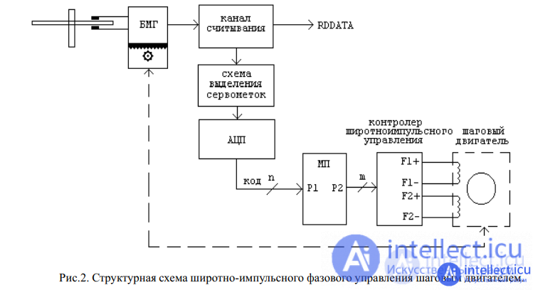
To move the magnetic heads by one cylinder, the control microprocessor sends an m code to the PFD controller, which leads to the MG movement by approximately one cylinder, after which the microprocessor reads code n from the servo marking circuit and compares this code with the reference value.
If the code does not match (due to an offset from the track), the code m is corrected and the process is repeated.
Control systems with a solenoid motor (voice coil) are the most complex, but thanks to the advent of single-chip servo modulators, it has become possible to use a solenoid drive in inexpensive, mass-produced HDD models. Nowadays, almost all manufacturers of storage devices have begun to use just a solenoid motor for positioning systems. Structural
a control system diagram with a dedicated servo surface is shown in Fig. 3., with a built-in servo format - in Fig. 4.
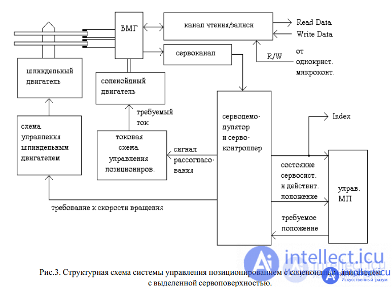
The principle of building a system with a dedicated servo surface is as follows: When a HDA is manufactured, special service information is recorded on one of the surfaces (usually the lowest surface of a disk package). The read-only magnetic head constantly reads the service information. The SI, amplified and filtered, enters the servo-modulator, where it is decoded and then the actual position of the magnetic head unit is determined. Based on the information received, an action is applied to the solenoid motor control device. Thus, tracking is carried out using the fine adjustment device.
Another task of the positioning system is to create a current pulse in each case when crossing the track. The initiator of such a pulse is the control microprocessor, which indicates to the servo controller the number of the required track. Based on this, the servo controller transmits the code of the required current pulse to the positioning control circuit, where its exact value is formed using the DAC. Let us first consider the operation of the fine control device, the task of which is to maintain the track once found as accurately as possible.
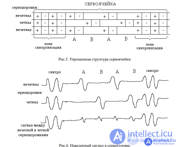
Position information is obtained using servo cells. Depending on the manufacturer, disc size, track density and servo cell complexity, the number ranges between 500 and 3000 per track. Figure 5 shows a simplified servo cell structure. Each cell consists of four changes in the direction of magnetization, called dibits. The cell is bounded on both sides by sync boxes. The position of the servo head is strictly between the even and odd servo tracks. In this case, the signal shown in Fig. 6 is induced in the servo head. The positioning electronics form an error voltage from this signal, which is obtained as the difference between the pulses indicated as A and B. If the head is now positioned absolutely correctly, i.e. strictly between servo tracks, then this error voltage will be zero.If the head is moved towards the odd track, then in the data signal pulse A increases and B decreases. In this case, a positive error voltage appears, and the servo system tries to compensate for it by moving the head towards the even track.

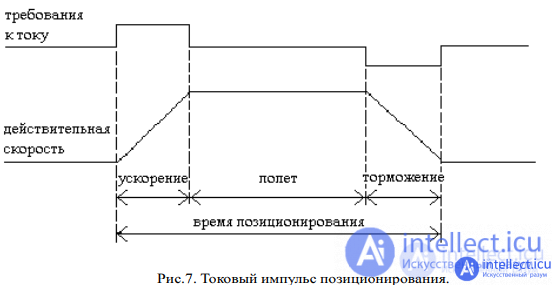
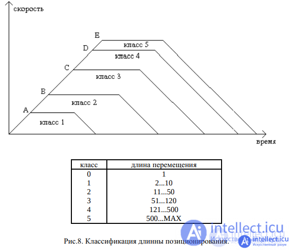
To move to the specified track, the positioning control circuit must generate a current pulse, as shown in Figure 7. After moving, the fine control system is activated to fine-tune the track. Depending on the length of the movement, the concept of positioning classes is introduced (Fig. 8), along which the current displacement pulses are formed. The more positioning classes a drive has, the faster the drive finds the desired track. In modern drives, the number of positioning classes is equal to the number of drive servo tracks - at the same time, each travel length has its own specific current pulse.
Servo information is placed in a completely different way using the “Embedded servo” principle . During HDA manufacturing, service information is recorded on each working surface with
labels. Micro-magnum format is widely used as standard, Fig.9.
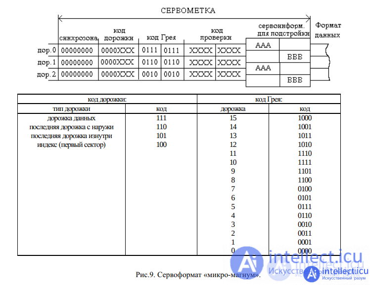
The servo system works like a dedicated servo surface system. The differences are
that the service information between the sectors is extracted from the drive data stream and is received in
portions. Therefore, after moving to the required cylinder (even when switching the head), it is necessary to
skip several sectors to fine tune to the track. When performing write / read operations
, so that the servo tag is not overwritten, the write signal to the channel comes from the servo controller only after
the servo tag is fully read and identified. When reading it, the servo controller generates
sector SEC / DRUN pulses, which are fed to the single-chip microcontroller, Fig. 4.
Источник: https://krzjctcqcwwsz457pdyzpqcqeu-intellect-icu.translate.goog/poisk-diagnostika-i-ustranenie-neispravnostej-ata-diska-9805

Comments
To leave a comment
Diagnostics, maintenance and repair of electronic and radio equipment
Terms: Diagnostics, maintenance and repair of electronic and radio equipment