Lecture
Pulse-width converters are a constructive part of pulse power supplies for electronic devices. We will analyze how to check a PWM controller using a multimeter, using the example of a computer motherboard.
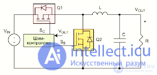
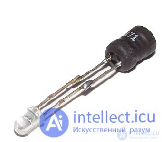
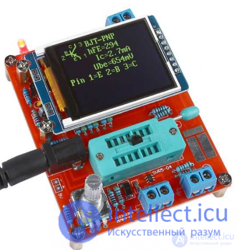
Using an ultra-fast and simple method, a faulty controller PWM unit can be identified mismatched by checking the corresponding throttles with a home-made device.
Let's remember a little theory. Around each transformer, or choke, with a significant number of turns, after turning on the power of the circuit, there is a magnetic field, and it is the greater, the more turns are at the winding of the transformer, or choke. If we bring another choke loaded with an LED to the winding of a transformer or choke connected to the device's network, then the magnetic field of the choke or transformer will penetrate the turns of our choke, and a voltage will appear on its terminals, which can be used, in our case, for indication of the operability of circuits in which there are throttles or pulse transformers. Of course, bring the probe as close as possible to the part being checked.


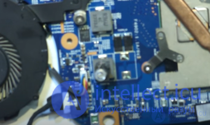
If, when the board is powered on, the protection is triggered, then you need to check the resistance of the stabilizer arms with a multimeter.

For these purposes, a radio component tester can also be used. If one of them shows a short circuit, that is, the measured resistance is less than 1 Ohm, then one of the key field-effect transistors is broken.

The determination of the broken transistor in case the stabilizer is single-phase is made on the basis that the faulty device shows a short circuit when checked with a multimeter.
If the stabilizer circuit is polyphase (this is how the processor is powered), then parallel connection of transistors is used.
Then, there are two ways to find the damaged element:
 solder the transistor and check the resistance between its terminals with a multimeter for breakdown;
The second method does not work in all cases.
If it was not possible to determine the broken element, you still have to evaporate the transistor.
Next, the damaged transistor is replaced, as well as the installation in place of all the radioelements soldered during the diagnostics process. After that, you can try to start the board.
It is better to perform the first power-up after repair by removing the processor and setting the appropriate jumpers. If the first start was successful, a load test can be performed by monitoring the temperature of the mosfets.
Malfunctions of the PWM controller can manifest themselves in the same way as the breakdown of the mosfets, that is, the power supply goes into protection. In this case, checking the transistors themselves for breakdown does not give a result.
In addition, the result of a violation of the PWM controller functions may be the absence of the output voltage or its inconsistency with the nominal value. To check the PWM controller, you should first examine its datasheet. The presence of high-frequency voltage in a pulsed mode, in the absence of an oscilloscope, can be determined using a quartz tester on a microcontroller.
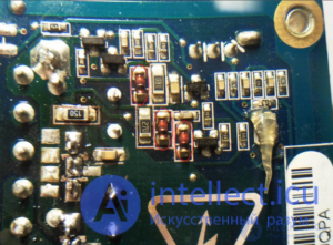
Search for the problem: inspection of the board, search for visible external damages; measuring with a multimeter the supply voltage of the microcircuit, the voltage at the keys (at the gates and at the output), at the output capacities. In ohmmeter mode, measure the load of the stabilizer with a multimeter, compare it with the typical value for similar circuits.
Possible reasons: the presence of a inhibiting signal at the corresponding input. Information should be found in the datasheet of the corresponding microcircuit. A malfunction may be in the power supply circuit of the PWM controller, internal damage is possible in the microcircuit itself.
Steps to determine the malfunction: external examination of the board, visual search for mechanical and electrical damage. To check with a multimeter, they measure the voltages on the legs of the microcircuit and check their compliance with the data in the datasheet, if necessary, replace the PWM controller.
The output voltage is significantly different from the nominal value. This can happen for the following reasons: break or change in resistance in the feedback circuit; malfunction inside the controller.
Troubleshooting: visual inspection of the circuit; checking the levels of control and output voltages and checking their values with datasheet. If the input parameters are normal, and the output does not correspond to the nominal value, replace the PWM controller.
When the PWM starts up, the power supply is shut down by protection. When checking the key transistors, a short circuit is not detected. Such symptoms may indicate a malfunction of the PWM controller or key driver.
In this case, it is necessary to measure the resistance between the gate and the source of the keys in each phase. An underestimated resistance value may indicate a driver malfunction. If necessary, the drivers are replaced.
Источник: https://pe6hotlwprsfznmserryhjl35i-intellect-ml.translate.goog/proverka-ispravnosti-shim-preobrazovatelya-9060

Comments
To leave a comment
Diagnostics, maintenance and repair of electronic and radio equipment
Terms: Diagnostics, maintenance and repair of electronic and radio equipment