Lecture
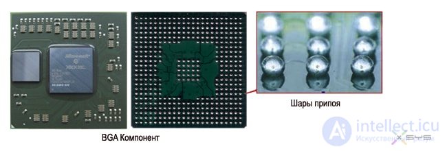
The term reballing (reballing from the English reballing - “treatment” of the dump of BGA chips) is a replacement of solder balls that are located under the electronic BGA components. It is part of the re-work process - repair of electronics (PCB, printed circuit boards) using a soldering station (air or infrared) and / or hot air gun.
Reballing is needed when a dump occurs at the points of contact between the chip (BGA) and the board (PCB). The component (chip) stops working due to a violation of electrical contact.
In most cases, the problem of the so-called chip blade occurs due to deformation during overheating or due to the use of low-quality solder.
In turn, the operation of electronics in conditions of constant overheating can lead to deformation and dumping of solder balls.
[icon name = "exclamation-circle"] This is why we strongly recommend that you professionally clean your laptop from dust and replace thermal paste at least once every 2 years (preferably once a year).
Prior to the adoption of the RoHS directive (this directive restricts the use of potentially hazardous elements in electrical and electronic equipment, in this case lead), manufacturers used solders containing lead. After the adoption of the directive in 2006, lead solders were banned, and companies were forced to use other alloys. As a result of this, since 2006, the number of marriage in electronics has increased several times.
Reballing is most often used when repairing laptops (motherboards) and repairing video cards , since the cost of the procedure is much less than the cost of an entire module. When replacing the north bridge, reballing is not performed if the chip immediately fell into place.
Video source: https://www.youtube.com/user/fineplacer
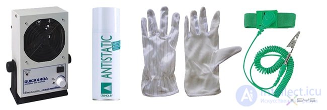
ESD protection
Static electricity is dangerous for BGA components!
Below is a small list of static protection tools (ESD Protection):
Dismantling BGA components is much more complicated than it seems at first glance! For high-quality dismantling, it is necessary to have a soldering station (preferably a professional infrared soldering station ), which includes: a thermostat, an upper heater on a tripod and a temperature regulator, preferably with the ability to work on a given thermal profile! After warming up the board, the BGA component must be quickly removed at the time of fusing the leads! You can remove it with mechanical or vacuum tweezers. (Vacuum is safer with less chance of damaging the board during removal!)
Tools and materials

Sequencing
Install the board in the frame holder or on the PTFE racks with the faulty component to the top, and place it on the thermostat of the soldering station.
Apply flux around the BGA component, cover the components around the chip with foil, and install a thermal sensor close to the BGA component to control the thermal profile.
Install the top heater over the failed component; set the solder thermal profile and wait for it to complete.
After the soldering process is completed, quickly remove the Component using vacuum or mechanical tweezers.
After removing the BGA component from the board, it is necessary to remove the remaining solder both from the board and from the component itself! (Actually this procedure is called debasing) There are many tools that allow you to remove the remaining solder from the BGA component. It can be both vacuum tools with hot air and soldering irons, there are also low-temperature wave soldering installations, which are more preferable in this case, they do not heat up the component very much, which implies that the chances of damaging the component by heating tend to zero!
Since soldering irons with temperature-controlled soldering are not so rare, we will describe the debinding process using a soldering iron with a sting.
Attention: The debolding process contains a lot of mechanical and thermal stresses that are potentially dangerous for the chip, so you should be careful.
Tools and materials

Additional Recommended Tools
Note: It is recommended to carry out the drying of the component; to remove moisture, it is recommended to do it before debolding.
Sequencing
Place the BGA component on the antistatic mat, side of the pads facing up. Apply the flux paste evenly to the BGA component. (Too little flux will make debolding difficult.)
Using a braid and a soldering iron to remove solder balls from Chip pads. Put the braid on the chip over the flux, then warm it with a soldering iron. Before you move the wicker along the surface of the chip, wait until its soldering iron warms up and melts the solder balls.
ATTENTION:
Do not push the chip with a soldering iron tip. Excessive pressure can damage the chip or scratch pads. For best results, clean the BGA component with a clean piece of braid.
After removing the solder from the surface of the chip, the chip Immediately clean with a cloth soaked in isopropyl alcohol. Timely treatment of the chip will facilitate the removal of flux residues.
When wiping the surface of the chip, remove the flux from it. Gradually move the chip by rubbing on a clean tissue areas. When cleaning, always support the opposite side of the chip.
Note:
1. Never clean the BGA chip contaminated tissue site.
2. Always use a new cloth for each new chip.
It is recommended that inspection was carried out under a microscope.
Check purity pads undeleted damaged site and solder balls.
Note:
Since the flux has a corrosive effect, it is recommended to conduct additional purification, if the chip Reballing not be made immediately.
Apply deionized water (water not having elekticheski charged particles. (Ions)) on the contact pads of the chip and rub them brush (can use conventional toothbrush). This will help flush residual flux off the chip. Then dry the chip with dry air. Recheck the surface (Step 4).
If the chip will lie for some time without the balls applied, you need to make sure. That its surface is very clean. Immersion of the chip in water for any period of time is NOT RECOMMENDED.

Tools and materials
Optional Recommended Tools
Before you begin, make sure that the stencil lock is clean.
Sequencing
Set the temperature profile for solder reflow equipment.
Place the stencil in the lock. Make sure the stencil is firmly locked. If the stencil is bent or wrinkled in the lock, the recovery process will not work. The wrinkle, as a rule, is a consequence of contamination of the latch or poor adjustment to the screen.
Use a syringe to apply a small amount of flux to the chip.
Note: Before you begin, make sure. that the surface of the chip is clean.
Using a brush, evenly distribute the flux on the side of the contact pads of the BGA chip. Try to cover each pad with a thin layer of flux.
Make sure that all pads are coated with flux. Try to apply the flux thinly and evenly, with a thick layer there will be poor contact between the solder balls and the contact pads.
Place the BGA component in the stencil holder, with the contact pads towards the top.
Put a stencil on the top, recall that the stencil is already in the latch (the top cover of the stencil holder), and fix so that the stencil is adjacent to the pads.
Pour the required number of solder balls onto the stencil, roll the balls with the inclined movements of the stencil holder, after the balls fall into place in the stencil, remove the excess with a brush.
Place the stencil in a hot convection oven or reballing station with hot air or IR, and start the reflow cycle.
In any case, the equipment used must be tuned to the thermal profile developed for the BGA chip.
Remove the latch from the oven or reballing station and place it on the conductive tray. Let the chip cool for about a couple of minutes before removing it from the latch.
After the chip has cooled, remove it from the latch and place it in the cleaning pan, with the side of the ball leads up.
Apply deionized water to the BGA stencil and wait about thirty seconds before proceeding.
Using thin tweezers, remove the stencil from the chip. It is best to start from the corner, gradually removing the stencil. The stencil should be removed in one go. If it doesn’t suddenly come off, add more deionized water and wait another 15 to 30 seconds before continuing.
Perhaps after removing the stencil, small fragments of particles or dirt will remain. Remove them with a needle or tweezers.
ATTENTION:
The tip of the tweezers is sharp, so it can scratch the solder mask on the chip if you are not careful.
Immediately after you remove the stencil from the chip, clean it with deionized water. Apply a small amount of deionized water and rub the chip with a brush.
ATTENTION:
Support the chip while brushing it to prevent mechanical damage.
Rinse the chip with deionized water. This will help remove small particles of flux and dirt left over from previous cleaning steps.
Let the chip dry in air. Do not wipe it with cloths or rags.
Use a microscope to check the chip for contamination, missing balls or flux residues. If you need to clean again, repeat steps 11 to 13.
During the BGA reballing process, the latch becomes more sticky and soiled. It is necessary to clean the flux residues from the retainer so that the stencil sits in it correctly. The process described below is suitable for both flexible and rigid latches. It’s good to use an ultra sound-cleaned bath for better cleaning.
Tools and materials
Optional Recommended Tool
Soak the BGA stencil retainer in warm deionized water for about 15 minutes.
Remove the retainer from the water and brush it.
Rinse the retainer with deionized water. Let it air dry.
After we did the reballing, we cleaned and checked the chip, you need to make sure that the contact pads on the board are clean of solder and dirt.
And only after checking to begin the installation of the component, for this it is necessary to apply a thin layer of flux to the pads to install the chip for further soldering. The location of the chip must exactly match the pads.
Release the upper heater and start the set thermal profile.

Comments
To leave a comment
Diagnostics, maintenance and repair of electronic and radio equipment
Terms: Diagnostics, maintenance and repair of electronic and radio equipment