Lecture
The basis of the laser printer is electrophotographic principle of image formation. The technology is based on the principle of dry electrostatic transfer. The essence of this principle is as follows: the light source shines on the pre-charged surface of the photosensitive shaft (photodrum, photo-photo). At those places where the light has hit, the charge changes and toner is then attracted to these places. Then this toner is dragged over by electrostatics on the paper on which it enters the oven, where it is fixed, under the action of high temperature and pressure. Prints made in this way are not afraid of moisture, resistant to abrasion and fading. The quality of this image is very high.
The structure of the laser printer is shown in Figure.
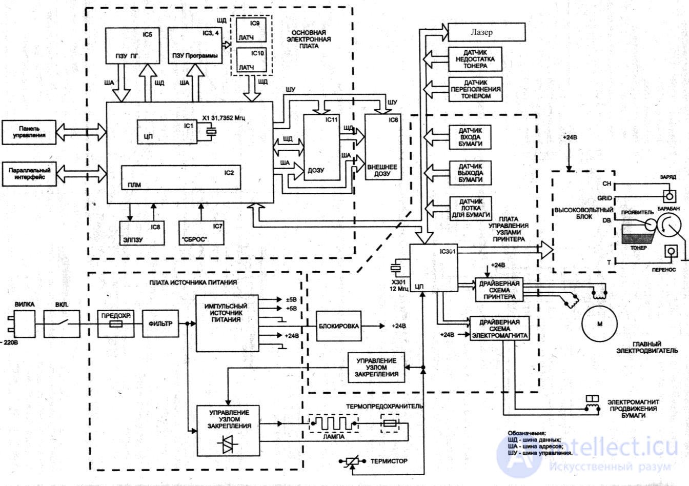
Figure 76 - Block diagram of a laser printer
The main elements of the printer are:
Features of the paper transport unit
The paper placed in the tray activates the paper presence sensor PS201, which informs the ECU about the presence of paper, and the printer is ready to receive data.
Having received the data in the formatter, the ECU turns on the laser scanner and the main engine and activates the SL001 paper feed solenoid.
The paper lift plate brings the front edge of the paper to the feed roller, the feed roller makes one turn, pushing the paper forward to the feed rollers.
Brake pads that have a friction coefficient with paper are higher than between sheets of paper and allow you to feed only one sheet to the feed rollers.
The draw rollers feed the front edge of the paper to the PS402 paper registration sensor, which informs the ECU that the paper is registered and beam modulation must be started to begin the exposure process. Sensor registration allows you to accurately combine the image on the drum with a sheet of paper.
Broach rollers push the paper further to the drum and the transfer roller under it.
After the image is transferred, the paper enters the stove and its leading edge activates the output sensor PS401, informing the ECU that the paper has reached the stove. The exit rollers direct the paper to the exit tray and the rear edge of the paper deactivates the exit sensor, informing the ECU that the paper has successfully left the oven.
Conditions for issuing a paper path error The processor will issue a paper error signal in the following cases:
Preventing and diagnosing printer problems
To carry out maintenance work on the printer, it is necessary to disassemble it by removing the outer plastic cover. Clean the inside of the printer from dust and toner.
Wipe rubber rollers with a liquid for the prevention of rubber surfaces (for example, Platenclene from Automation Facilities), and mirrors -
liquid for the prevention of optical surfaces (Safeclens company AF or similar means from Xerox, Katun).
The inside of the printer frame can be blown out with a compressor. Plastic casing is best washed with liquid soap or special formulations like Foamclene (AF).
The main types of faults can be divided into three groups:
The faults of the electronic circuit are mainly due to the aging of the elements.
Fault diagnosis is performed in the following sequence:
For diagnostics, you can use the display error codes on the front panel.
| What the printer shows | Error description |
|---|---|
 |
ROM / RAM Error : distribution and reading error from computer. Replace additionally installed printer memory, replace printer formatter. |
 |
Fuser Error : printer fuser error. Check the contacts of the thermal node and the thermistor thermistor, replace the thermal node (see below PPS) . |
 |
Beam Error : General printer malfunction. Turn off-turn on the printer, check the connection of the laser scanner loops, check the laser scanner, replace the DC controller. |
 |
Print Engine Error : General print error. Disconnect the LPT interface cable (Centronix), remove the printer formatter, replace the formatter, replace the DC controller. |
 |
Printer Laser / Scanner Error : laser scanner error. Almost always - the replacement of the laser scanner. |
 |
Firmware Error : fatal formatter error. Replacing formatter. |
 |
DIMM Error : additional memory installed error. Replace additionally installed memory. |
 |
Document Scan Engine Error : document scan error through the optionally installed scanner option. |
 |
Depending on whether the printer is equipped with an additional scanner option, the fault includes: 1) if equipped, the additionally installed scanner is defective; 2) if not equipped, there is an error in the paper output-output sensors, laser scanner blinds, cartridge photodrum contact, printer cover microswitch malfunction. |
PS The indication of errors described in the “User’s Guide”, which comes with each printer, is not considered here.
PPS Printers have a common error, which is similar to a malfunction of the thermal node (fuser), but due to the fact that the laser shutter does not open.
Basic faults kinematics and mechanics
Main faults in kinematics and mechanics
These faults occur both because of normal wear and tear on moving parts of the printer, and after preventive maintenance due to the engineer's negligence during reassembly. The LJ-1100 model has a lot of thin and shaky latches, which can be easily damaged during assembly and disassembly of the device. It is worth paying attention to the paper feed unit, namely, the cam guide of the snap-in plate (Pick UP Roller Shaft), the drive mechanism of the snap-in plate, the paper exit switch, cable for connecting the scanner option, decorative paws. These places are especially prone to malfunctions after disassembly-assembly.
Details on the main faults - in table number 2:
| Nature of the fault | Debugg |
|---|---|
| The printer takes many sheets from the receiving tray. | The cardinal measure to solve this malfunction is to replace the sheet separator, but variants of rubber plywood are possible. To do this, it is necessary to pry the rubber plate of the separator with a thin slotted screwdriver, carefully separate it from the plastic base, and, turning it 180 degrees, firmly press it to its original place. If a clear drying of the gum of the separator is noticed, then such a part is not subject to recovery. |
| The printer does not take paper from the input tray. | The printer feed roller is defective or severely dirty. You can try to restore its properties with a liquid for the prevention of rubber surfaces, but it is better to replace the roller. Also, the appearance of this malfunction may occur as a result of the loss of one of the separator springs or the snap-off plate. |
| When installing the printer, a crash is heard on the left side, the printer comes on alert, and does not serve a sheet when trying to print. | This malfunction is due to a Pick UP Roller Shaft breakdown or a loosening of the paper feed cam latch. Accordingly, you should either replace the Pick UP Roller Shaft, or reinforce the cam latch. |
| When installing the printer, a crunch is heard in the front of the printer. When printing, there are black spots. | The fuser fuser's thermal film has failed (usually torn). It is possible to solve this problem by replacing the thermal film, but the replacement of the thermoelement assembly will be more correct and more durable, since Toner particles, falling on the thermal strip, destroy it, which entails its failure. |
| When printing, places of light image or white stripes are observed vertically. | Usually this is the contamination of the optical system of the laser scanner, but also a malfunction may occur from the use of cartridges or refilled, or of doubtful origin. Respectively clean the laser scanner optics or replace the cartridge. |
| Ribbed black stripe on the edge of the sheet vertically. | Defective cartridge photo drum; change the drum unit or the entire cartridge. |
| When printing, blurred image locations are observed. | Printer Transfer Roller Faulty. Replace the roller. |
| Printed sheet does not go up. | Paper exit switch broken, replace. |
| When printing, black toner flakes are observed on the right. | Cartridge leakage is broken; He pours toner. Replace the cartridge, to make preventive maintenance of the thermal node. Check the integrity of temofilms. |
| When installing the printer can be heard howling scratch on the left. The printer does not print. | Burst gear main drive. Replace the gear, remove the old grease from the drive and apply a new one. Lubrication should be used only for plastic drives (thick, white). Manufacturer does not matter. |
| The first sheet is printed normally, and the second passes one third after registration and stops. Paper Jam Indication | Faulty sheet exit sensor. Reinforce the sensor spring with an additional loop. Perform maintenance or replacement of optocouplers. If the fault is not resolved by replacing the optocouplers, change the DC controller. |
| Additional scanner option is not installed. | Damaged scanner cable. Replace the cable. If after replacing the cable the option is installed, but does not work, then it is necessary to replace the printer formatter. |

Comments
To leave a comment
Diagnostics, maintenance and repair of electronic and radio equipment
Terms: Diagnostics, maintenance and repair of electronic and radio equipment