Lecture
Modern raster video monitors (VMs) for computers use construction principles similar to those used in television technology, but differ from the latter in the absence of a radio path and circuits for processing video signals (a color unit). Below in Figure 1 is a generalized block diagram of a VM, which shows all the functional units and control elements necessary for its operation.
The main element of the VM is a CRT with a deflecting system (personnel deflection coils - QC and lowercase - SC). All other elements shown in the block diagram are used to ensure the operation mode of the CRT and the coordination of signals from the computer.
Since color VMs should provide for the periodic demagnetization of a CRT mask to maintain "color purity", they are equipped with a demagnetization loop that works automatically every time the VM is turned on. In high-quality VMs, an additional possibility is provided to enable demagnetization at any moment of operation, for which the "DEGAUSS" button is installed on the front panel.
As in a conventional TV, for receiving a raster on the screen of a VM, nodes for horizontal and vertical scanning are necessary. The master oscillators for these nodes are usually strongly associated with the control unit, so they are shown together in the block diagram.
Information from the computer is fed to the input connector of the VM and then to the video signal processing unit for conversion into signals with the control voltage levels of the CRT modulators. For VMs of type CGA, MDA, MCGA, HGC and EGA, the functions of this node include the additional conversion of input video signals with TTL levels to RGB (matrixing) signals for decoding color and brightness information coming from a computer. The component of the video signal processing unit also includes a CRT board, which serves to connect directly to the CRT base. Terminal video amplifiers are usually located on this board, and other video signal processing node circuits can be located on it or on the main board of the VM.
The power supply unit of the VM produces all the necessary voltages for powering the units shown in the block diagram, except for the accelerating voltage HV for CRT, which, to ensure greater stability, is traditionally produced in the high-voltage unit of the horizontal scanning unit. In the power supply unit of a color VM, the demagnetization loop power supply circuits are usually integrated.
The control unit serves to control input signals from a computer (sync pulses) and set the operation modes of the scan nodes, video signal processing, and the power supply unit for maintaining and correcting the set image mode. Since information about video modes from a computer enters the VM as a combination of polarities of clock pulses (for simple modes) and their frequencies (SVGA modes), the control node performs a rather complicated task of determining sweep parameters and controlling other nodes. The functions of the control unit also include ensuring the protection of the CRT from emergency situations and ensuring the standby mode to save power (GREEN mode) when the VM is not used by the operator. In modern VM models, microprocessors with a set of specialized microcircuits are increasingly used in the control node, which ensure the preservation of all installations and simple control for the user.
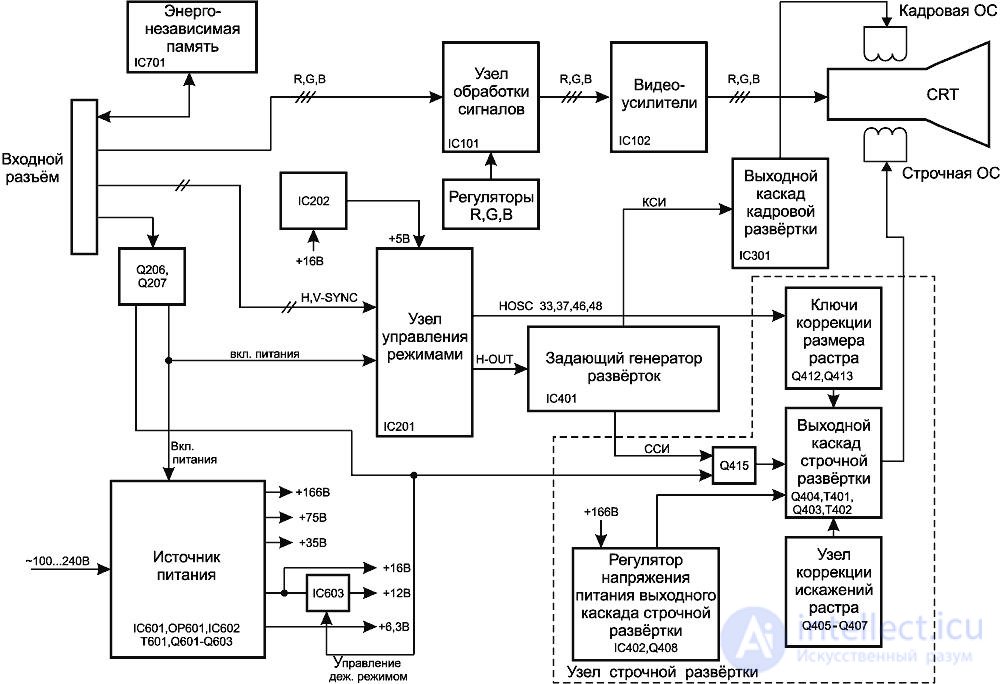
Figure 53 - Monitor flowchart

Comments
To leave a comment
Diagnostics, maintenance and repair of electronic and radio equipment
Terms: Diagnostics, maintenance and repair of electronic and radio equipment