The frame scanning node (VL) of the VM serves to power the frame coils of the deflecting system of a CRT using a sawtooth current.
The RC node is not an energetically intense device — there are no high voltages and high-power impulse currents in it, for this reason malfunctions occur rarely and usually due to aging of the elements or negligence during repair.
The schema contains the following elements:
- master oscillator (V OSC) capacitor C2 determines the frequency of the generator);
- Voltage-adjustable saw power amplifier (RAMP CEN);
- power amplifier (POWER AMP);
- additionally a reverse pulse amplifier (PUMP UP), which charges the capacitor C4 and connects it to the output stage power supply circuits, providing an almost two-fold increase in the voltage at the beginning of the forward sweep stroke and, accordingly, high linearity;
- The feedback circuit C11, Roc - provides stabilization of the gain of the amplifier.
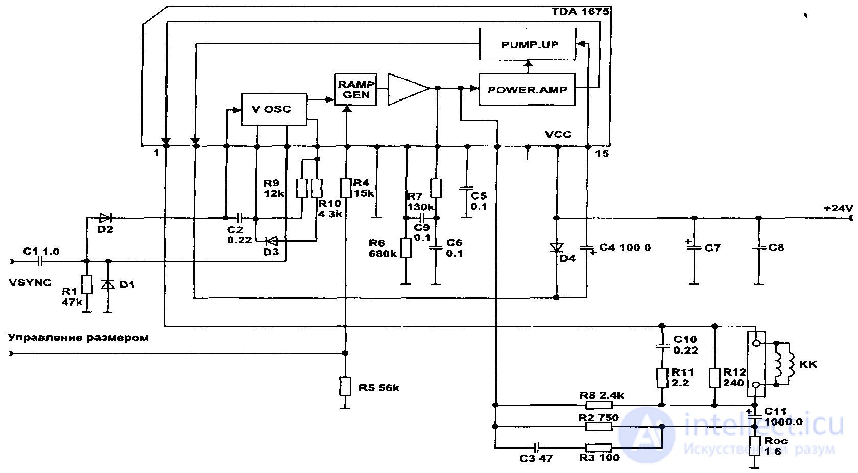
Figure 65 - Typical block diagram of the frame scanner Diagnostics of faults in the node KR
Defects in the CR node are usually diagnosed from a raster image and have the following symptoms:
- There is a bright bright horizontal strip on the screen, which indicates the absence of a sweep.
- The raster completely fills the screen, but there is no synchronization.
- On a stable raster, when testing programs are running, vertical linearity distortions are observed.
- The size and vertical position controls do not work or do not correspond to the enabled mode.
Troubleshooting in the CR node begins with
- supply voltage checks
- control the temperature of the body of the chip. The operating temperature of an IC, including an output amplifier (TDA1175, TDA1675, TDA4866), can be quite high, but should not exceed 70 ° C.
In the case of the complete absence of a scan on the raster they check the operation of the master oscillator by monitoring the signal on the time-keeping capacitor and on the input of the output amplifier with an oscilloscope. If these signals are present, then check the passage of the saw signal through the output amplifier to the connector connection of the deflecting system. There may be breaks in the coupling capacitor or a current feedback resistor, as well as a malfunction of the output amplifier in the IC.
In the absence of synchronization, the passage of a sync pulse is checked before entering the The master oscillator IC may have a malfunction in the control unit.
Vertical linearity distortions are estimated by the image when running test programs, for which use a grid image.
Most of these distortions are due to electrolytic capacitor defects in the boost circuit (C4) or in the master oscillator (C2) - the capacitors lose their nominal capacitance or leakage current appears.
The remaining faults related to the lack of action of adjustments on the front panel when trying to resize the raster vertically or to shift it, may be caused by defects in the potentiometer itself or malfunctions in the control unit. In this case, check the corresponding circuit with an ohmmeter, monitor the voltages with a voltmeter or an oscilloscope and determine the faulty element.
After fixing all the faults that have appeared in the CR node, all the necessary raster parameters are set with the help of trimmers.

Comments
To leave a comment
Diagnostics, maintenance and repair of electronic and radio equipment
Terms: Diagnostics, maintenance and repair of electronic and radio equipment