Lecture
In most cases, malfunctions in REA occur due to the failure of active and passive electrical radio elements (ERE). Active EREs include integrated circuits (ICs), transistors, thyristors, zener diodes, etc. Passive EREs include resistors, capacitors, transformers, chokes, etc.
When carrying out repairs, it is necessary to be able to monitor the performance of active and passive EREs, both outside the units (modules) and in their composition, i.e. without watering them from the boards, as well as be able to identify faults in the electronic radio electronic device.
In most cases, transistors are used in analog REDs, such as amplifiers, generators, voltage and current stabilizers, amplitude limiters, and many others. The performance of bipolar transistors can be checked with an ohmmeter by measuring the resistance between the base and the emitter, the base and the collector in both directions. Values of resistance values according to the “low” / “high” principle are shown in fig. 1.14.
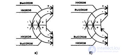
Fig. 1.14. Measurement of resistance in pnp (a) irpn (b) transistors
It should be noted that there are cases when the section of the collector-emitter circuit is short-circuited, despite the fact that both transitions of the transistor are intact. Therefore, first you need to check whether there is a short circuit in the collector-emitter circuit.
A transistor with a periodic break in the junction may be temporarily operable when it is checked with an ohmmeter. Therefore, it is more reliable to monitor its DC operation modes in various switching circuits (Fig. 1.15).
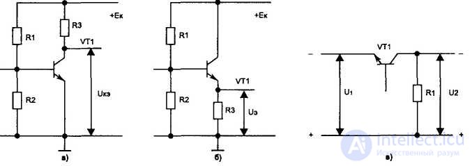
Fig. 1.15. DC power transistors: a) circuit with OE; b) scheme with OK; c) scheme with OB
Faults in the transistors included in the scheme with a common emitter (OE).
1. ike = 0 - short circuit between the collector and the emitter or the transistor is in saturation due to faulty ERE or hidden mounting defects (SDM) circuit. The saturation state of the transitions of the transistor is easy to determine if you shorten its base output to the common wire. In this case, for a working transistor, the specified voltage will become close to EC due to the fact that the “base-emitter” and “base-collector” transitions are closed and the transistor is tightened (there is such a term) to the “point”. If this does not happen, the transistor is faulty and must be replaced by a healthy one.
2. Eke = Ek - breakage of one of the transitions of the transistor or the transistor is in the cut-off mode due to faulty ERE, blocking voltage or SDM.
In this case, first of all, it is necessary to check the voltage between the base and Zmitter, which should be approximately equal to the following values:
ЕГбэ + (0,6 - 0,7) V - for the transistor pnp,
ЕГбэ - (0,6 - 0,7) В - for the pn transistor.
If the EGbE voltage is significantly different from the specified one, then it is necessary to check the ERE and the circuit from which the blocking voltage is applied to the base of the transistor.
Faults in the transistors included in the scheme with a common collector (OK)
1. EGE = 0 - break of one of the transitions or the transistor is locked.
2. EGE = EC - the transistor is “pierced” or is in saturation mode.
Saturation mode is defined as in the scheme with OEL
Faults in the transistors included in the scheme with a common base (OB)
E EG 2 = 0 - break of one of the transitions of the transistor or the transistor is locked.
2. EG 2 = EJj - transistor “pierced” or is in saturation mode.
The saturation mode is determined in the same way as in the circuits with OE and OK by “shorting” the base terminal of the transistor to the common wire.
When repairing the RIP, it is necessary to know how these or other circuit elements affect the magnitude of the voltage at the terminals of the transistor. For example, consider the resistive amplifier circuit (Fig. E16).
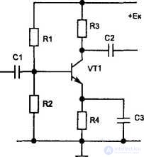
Fig. 116. A generalized switching circuit of the transistor in the amplifier stage
Symptom 1: low voltage on the collector of the transistor VT1.
Causes: a decrease in the supply voltage Ek, “breakdown” of the transistor VT1, increased leakage currents of capacitors C1, C2, Sz, break in the resistors R2, R3.
Symptom 2: increased voltage on the collector of the transistor VT1.
Causes: breakage of one of the transitions of the transistor VT1, breakage of resistors Rl, R4. You can check the transistor saturation mode by parallel connection to the resistor R1 of an additional resistor of close rating. In this case, the voltage on the collector of the transistor should decrease.
In radio devices, both analog and digital integrated circuits are widely used. Their use improves the reliability of devices, reduces the number of radio-radio elements, and, therefore, simplifies their repair. However, when operating the RIP, the microcircuits often fail.
The conclusion that the microcircuit is faulty can only be made after checking all EREs connected to it. First, control the mode of operation of the chip by DC. The low voltage on one of the microcircuit pins may be due to the presence of a leakage capacitor connected to this point, which can be turned off during the test. After that, using an oscilloscope to monitor the correctness of the signal.
For digital microcircuits of the K155 series, KPZ and a number of others, the supply voltage is +5 V, the low level voltage (logical zero) is no more than +0.4 V, the high level voltage is (logical unit) not less than +2.4 V (typical value of +3.5 V).
The monitoring of the operability of a digital microcircuit can be shown by the example of a logical element 2И-НЕ (fig. 1.17).
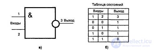
Fig. 1.17. The logical element 2I-NOT (a), the state table of the element 2I-NOT (b)
As can be seen from the state table of the logic element 2I-NOT, the output 3 will result in a logical zero only in one case when there are logical units at inputs 1 and 2. In any other case, when both or one of the inputs 1 and 2 will be a logical zero, the output of 3 will be a logical one. Based on this, it is possible to simulate the mode of operation of the chip according to the state table. Deviations in the operation of the chip from the values given in this table indicate that it is faulty.
The performance of the chip can be checked in a dynamic mode, using an oscilloscope, controlling the passage of pulses generated and connected to its inputs. When the element is in dynamic mode, the logical unit at one of its inputs is the resolution for passing the output pulses to the second input. Logical zero is a ban for them. You can generate a logic zero signal on any of the chip inputs by connecting the corresponding output to the common wire. The signal of a logical unit can be formed by disconnecting this chip output from the rest of the circuit. If you disconnect both inputs of the considered chip, then they should have a constant voltage of about +1.5 V.
When checking the chip, you also need to make sure that its output is not shunted by the subsequent cascade (the input of another chip). To do this, they usually neatly cut the printed track, and after carrying out the necessary checks, they carefully solder, reestablishing contact.
Malfunctions in digital circuits
The low-level voltage at the output of the chip, independent of the input signals, can be in two cases: either a short circuit in the installation, or the chip is faulty. With short circuit in the installation, the voltage at the output of the microcircuit is close to zero, whereas in the event of a malfunction inside the microcircuit, it corresponds to a low logic level of 50–300 mV.
In the case of a short circuit in the installation, a characteristic “ringing” is observed at the output of the microcircuit, caused by the resonance of the parasitic inductance and the capacitance of the installation when switching the output stage transistors. The amplitude of the “ringing” signal is from tens to hundreds of millivolts.
Constant high-voltage level at the output of the chip, independent of the input signals, usually occurs when the common wire is broken (poor soldering of the output or an open circuit inside the chip).
Low voltage high logic level at the output of the chip can be caused by several reasons. If the logic function of the microcircuit is preserved, then it is likely that some EREs are faulty in the microcircuit. If the logical function is completely violated, then most likely the fault is an open circuit or an open circuit.
Breaks can occur both inside the chip and outside of it due to poor output soldering. An overvoltage of a low logic level (up to 1.7 V) is usually observed with a sharp increase in the load current of the TTL circuit or with breaks in the internal structure of the microcircuit. This malfunction is sometimes misleading by the fact that it “disappears” when disconnecting loaded TTL circuits, since its appearance requires the presence of a current flowing into the microcircuit on the output side. Increasing a low logic level to 1.1 Vs while preserving the logic function of the chip can be if the common wire is broken (poor contact soldering or breakage inside the chip), if one of its inputs is grounded (permanently or only during this test) via the output of another chip.
Violation of the logic function at normal low and high logic levels occurs when the chip goes out of order or when the outputs of two gates are short-circuited.
If the thyristor is not connected to the circuit, the resistance between any pair of its electrodes (anode, cathode, control electrode) must be large regardless of the polarity of the ohmmeter, except for the resistance “control electrode-cathode” having a small value at a positive potential of the control electrode .
To control the thyristor performance, we can recommend the circuit shown in fig. 1.18.
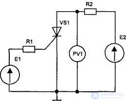
Fig. 1.18. Thyristor health monitoring circuit
The resistance value R2 must meet the requirements.
1ud
where E2 is the voltage less than the switching voltage of the thyristor (Unep), 1up is the holding current at Euek = O V, Imax is the set forward current.
Monitoring the thyristor is performed in the following sequence:
1. Set the voltage Eue = O V before connecting the source E2.
2. Connect the E2 source to the thyristor.
3. To control the voltage Jak, the value of which should be close to the source voltage E2.
4. Smoothly increase the value of the voltage Eue and monitor the readings of the voltmeter PV1. When the thyristor turns on, the voltmeter should show a value close to zero, i.e. 
5. Smoothly reduce the voltage of Eue to zero, the voltage between the anode and the cathode of the thyristor will remain unchanged, i.e. 
6. Restore the original value of the voltage of the power source E2. If Eue = 0 V, then the voltage EGak should be high.
7. To check the switching voltage of the thyristor Unep, connect the control electrode with the cathode and gradually increase the voltage of the E2 source until the voltage of the EGak is low. The magnitude of the voltage source E2, in which the voltage EGak becomes low, is equal to the switching voltage of the thyristor EGper.
8. To check the reverse voltage Ehp, you should change the polarity of the source E2, set the resistance value of the resistor R2 10 times greater than before (to limit the reverse current) and repeat the test of the thyristor.
Diodes in electronic devices are used for rectifying (detecting) voltage, protecting transistors (microcircuits) against input overloads, switching voltages, frequency conversion. The performance of the diode can be checked with an ohmmeter, connecting the positive probe with the anode, and the negative - with the cathode of the diode, which corresponds to the direct inclusion. The resistance of the diode at the same time is small (tens of ohms). When a diode is connected in the opposite direction, its resistance is large (hundreds of ohms).
If you monitor the performance of the diode in the module, when an electric current flows through the diode, then when measuring the voltage drop on it you can get the following results 1 for healthy germanium diodes between the anode and cathode, the voltmeter will show a voltage approximately equal to ЕГ = (0.3 - 0 , 4) B, and for silicon EG = (0.6 - 0.7) V.
The main faults in the diodes are short circuits, breaks and changes in the parameters of the voltage.
If the diode is short-circuited, then an ohmmeter will show low, close to zero, resistance in the forward and reverse switching. In the event of a break, an ohmmeter in both directions will show great resistance (close to infinity).
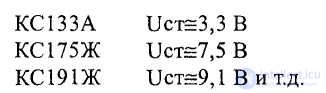
The health of the zener diodes, which are biased in the forward direction, is monitored by checking the magnitude of its resistance in the same way as that of the diodes. To control the health of the zener diodes, we can recommend to assemble the circuit shown in fig. 1.19.
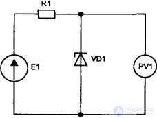
Figure 1 19 Scheme for monitoring the health of the zener diodes
Example. Check the performance of the silicon diode KS156A, if E1 = 24 V
1. Calculate the value of the limiting resistor R1.
According to the second law Kirchhoff:
E1 = U r1 + Uct,
where ЕГст - voltage stabilization of the Zener diode VD1, equal ЕГст = 5.6 V.
Accept current stabilization equal to 1CT = 3 mA, then
U R1 = 24-5.6 = 18.4 V
U r1 = Ict-R1 = 18.4 V,
from where: Rl = 18.4 V / 3 mA ~ 6.1 kΩ.
Choose Rl = 5.6 kΩ, since 1st article = ZmA
When testing Zener diodes without watering them out of the module, the voltage between its anode and cathode is measured, which should be approximately equal to Uct, for example:
If the voltage  then the zener diode is short-circuited, if this voltage is significantly
more than the voltage stabilization, most likely in the Zener diode there is a break.
Resistors are the most numerous radio elements in the RIP circuits. Check the resistance value of the resistors using an ohmmeter. The main problems with fixed resistors are an increase in the resistance value. This is most often observed in high-resistance (hundreds of kOhms or more) or low-resistance (units of ohms) resistors.
A break in fixed resistors is most often detected by visual inspection (color failure, black transverse coloring, etc.).
The main malfunctions of variable resistors are intermittent breaks in them due to poor contact of the slider with the resistive layer or due to wear of the resistive layer, as indicated by the inconsiderable (jerking) progress of the ohmmeter's arrow when the resistor slider moves.
A typical failure of a variable resistor is also a short circuit to the case when the resistor is installed on a grounded chassis or on the metallized part of the printed circuit board connected to the case.
Capacitors, like resistors, are mass passive EREs in RIP circuits. The share of capacitors accounts for a significant number of faults, and their finding can be quite difficult. The main malfunctions of fixed capacitors are breakdown (break) and a decrease in capacitance.
In electrolytic capacitors, a significant decrease in leakage resistance leads to a violation of the operating mode of transistors and microcircuits. The difficulty in detecting a decrease in leakage resistance in capacitors is that it may manifest under voltage when the device is running.
Reducing the capacitance of the capacitors in the smoothing filters leads to an increase in the ripple of the rectified voltage, which is unacceptable during the operation of the RIP.
A change in the capacitance of capacitors in the circuits inevitably leads to a change in the frequency response, and sometimes to self-excitation of the stages. This especially affects the operation of wideband oscilloscopes, where it is impossible to sacrifice bandwidth.
Breaks in separation capacitors generally lead to a loss of electrical signal. Breaks in fixed capacitors can be detected using an oscilloscope. If the signal and grounding probe of the oscilloscope is connected through a working capacitor, the pickup should decrease or disappear altogether. The breaks in the capacitors can also be determined by connecting the generator to the oscilloscope through a capacitor under test. The absence of an electrical signal on the CRT screen indicates that there is a break in the capacitor.
Electrolytic capacitors for the absence of a break can be checked in the following way: observing the polarity of the ohmmeter, connect it to the tested capacitor. At the first moment, the arrow should quickly deflect to the right (toward low resistances), and then slowly return to the left (toward higher resistances). A capacitor break can also be determined by connecting a serviceable capacitor to a DC voltage source. At the same time, a characteristic click should be heard, and a small spark will slip through his conclusions.
Additional signs of electrolytic capacitor malfunction are body bulging, electrolyte leakage, heat during operation, etc.
The main faults in transformers and chokes are winding breaks, inter-turn short-circuits, short-circuits of one winding to another, short-circuiting of windings on the case, etc.
Check for a break is made in a simple way using an ohmmeter. In the operating RIP, the breaks of the windings in the transformers or inter-turn short circuits in them lead to the fact that the voltage at the terminals of the transformers is either completely absent or is greatly underestimated.
The presence of a short-circuited coil with an ohmmeter cannot be determined. It is possible to determine the short-circuited turn in the transformer by collecting a simple circuit shown in fig. 1.20.
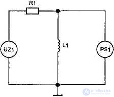
Fig. 1.20. Scheme for determining the short-circuited coil in the transformer
At the output of the sinusoidal oscillation generator UZ1, a frequency of 1 kHz is set, and a signal is fed through the resistor R1 to the tested winding L1. This is evidenced by the site https://intellect.icu. The voltage across the winding is controlled by the PS1 oscilloscope. The appearance of differentiated pulses on the winding L1 indicates the presence of a closed loop in it.
In addition, it should be remembered that the existence of a short-circuited coil in a winding, as a rule, leads to heating of the transformer.
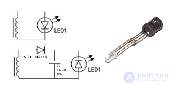
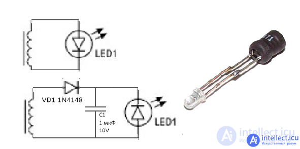
Also, a fairly simple way to check the operability of a transformer or throttle without dismantling is to use such a device consisting of a diode and throttle. when a drosel or transformer is introduced into the magnetic field, such a device will glow.
продолжение следует...
Часть 1 Malfunctions of active and passive radio radio elements

Для закрепления теории предлагаем пройти тесты по диагностике неисправности электро элементов https://intellect.icu/proverka-radioelementov-diodov-tranzistorov-kondensatorov-termistorov-i-optopar-3260
Так же для расширения понимания происходящих процессов рекомендуем прочитать и понять воздействие внешних факторов на работоспособность электро элементов
https://intellect.icu/vliyanie-vneshnikh-faktorov-na-nadezhnost-elektronnoj-apparatury-i-komponentov-tepla-kholoda-vlagi-radiatsii-degradatsiya-poluprovodnikov-9063
и прочитать про алгоритм поиска неисправностей
https://intellect.icu/razrabotka-algoritma-diagnostiki-i-poiska-neispravnostej-899
https://intellect.icu/3-1-3-algoritmy-nakhozhdeniya-neispravnostej-bloka-pitaniya-pk-3271
https://intellect.icu/sostavlenie-algoritma-otyskaniya-neispravnostej-900
Методы поиска неисправностей
https://intellect.icu/poisk-neispravnostej-metody-poiska-neispravnostej-a-takzhe-prichin-nerabotosposobnosti-elektronnykh-ustrojstv-3299
еще интересное понятие конденсаторной чумы — название проблемы повышенной частоты отказов алюминиевых электролитических конденсаторов в период с 1999 года по 2007 год, созданных в основном тайваньскими производителями . Проблема была спровоцирована неправильным составом электролита, который генерировал водород и вызывал коррозию. Это сопровождалось повышением давления внутри конденсатора и нарушением его целостности.
Comments
To leave a comment
Diagnostics, maintenance and repair of electronic and radio equipment
Terms: Diagnostics, maintenance and repair of electronic and radio equipment