Lecture
In order to be able to identify a faulty cascade by the external manifestation of a particular TV malfunction, it is important to understand the principle of the TV receiver, the purpose of all the cascades and their interaction. The structural diagram of the TV allows you to quickly understand the functional composition of the TV for individual nodes and understand the order of their interaction with each other.
So, the block diagram of the TV is a simplified circuit diagram in which, for convenience and clarity, the functional units of the circuit of the TV receiver are combined into separate blocks indicating their connections with each other.
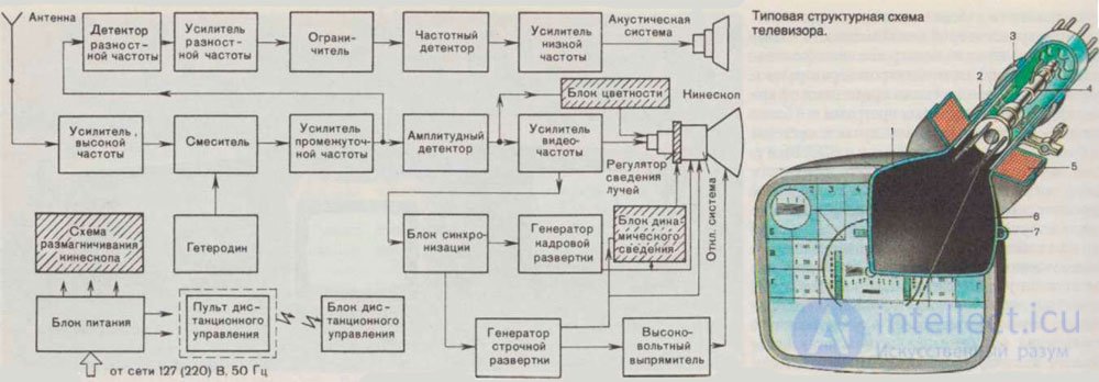
Over the past decades of development, television technology has undergone significant changes. From black and white TVs, to color and finally to digital LCD and plasma panels. Accordingly, the structural scheme was also changed. Rather, it did not change, but was supplemented with new blocks. So in color TVs appeared in addition: the color unit, the remote control unit, the switching unit of external devices. In LCD TVs, the scheme is somewhat more complicated.
This scheme applies not only to semiconductor black and white TVs, but also to tube ones.
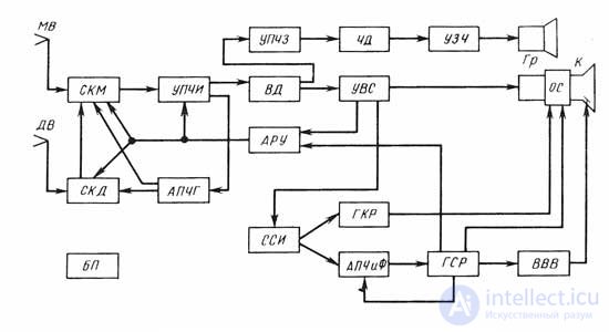
The block diagram of the TV in a simplified form consists of the following blocks:
SCM, SKD - meter and decimeter channel selector
UPCHI - Amplifier of the intermediate frequency of the image - After amplification and conversion in the PTK block (SKM and SKD), the image and sound signals are sent to UPCHI. The oscillation frequency of the local oscillator in the PTK block is chosen higher than the frequencies of the received signal, therefore, after conversion, the carrier of the intermediate frequency of the image (38.0 MHz) turns out to be higher than the carrier of the intermediate sound (31.5 MHz).
UPCHZ-intermediate frequency audio amplifier
APCG - Automatic adjustment of the local oscillator frequency
A high-quality image in first-class TVs can be realized by fine-tuning the local oscillator input devices to the desired frequency. With this setting, the highest image clarity, the absence of phase distortion and high sound quality is ensured. Fine tuning of the local oscillator is necessary for maximum suppression of interference from neighboring television channels.
All first-class TVs provide manual and automatic local oscillator frequency adjustment. Using manual tuning, you can correctly tune when receiving a test chart, while receiving gear, fine tuning is difficult. Automatic adjustment is needed, since the heterodyne frequency of input devices changes as the TV warms up, the supply voltage changes, the channels are switched, and other destabilizing factors are affected.
The automatic tuning of the local oscillator frequency (APCG) has a well-known feedback circuit consisting of two main devices: a discriminator and a control element. The input of the discriminator, whose functions on the TV performs the phase discriminator, the intermediate frequency voltage is applied. When the TV is fine-tuned, the voltage at the discriminator's output is zero, when the local oscillator frequency deviates from the nominal (38.0 MHz) control voltage appears, the magnitude and polarity of which is proportional to the detuning. This voltage is applied to a control element whose functions on the TV are performed by a varicap connected to the local oscillator circuit in a PTC unit. By acting on the varicap, the control voltage causes a change in the frequency of the local oscillator in the direction opposite to the initial detuning.
However, the APCG cannot nullify the initial detuning, and as a result there remains a residual detuning, which is the smaller, the greater the auto-tuning coefficient. On TVs, an APCG circuit with an amplifier at an intermediate frequency and a DC amplifier is often used, providing a residual detuning of no more than 50 kHz at an initial 1.2 MHz.
AGC - Automatic gain control , AGC (English Automatic Gain Control, AGC) - the process by which the output signal of a device, usually an electronic amplifier, is automatically kept constant by some parameter
АПЧиФ - automatic adjustment of frequency and phase . In televisions, the horizontal clock master oscillator is synchronized automatically by adjusting its frequency and phase to exactly match the frequency and phase of the clock pulses transmitted by the telecentre.
The ACHS & F module steadily synchronizes the horizontal scan when there are weak input signals commensurate with the TV's own noise, and reduces the effect of impulse noise. This is especially important for televisions with large screen sizes, on which even small curvatures of vertical lines in the image are visible to viewers. In the phase detector, which is part of the AFC & A scheme, the phases (frequencies) of the sync pulses of the incoming signals and the oscillations of the horizontal oscillator master oscillator are compared. At the output of the phase detector, a constant voltage is formed, the amplitude and polarity of which is proportional to the phase shift of the compared pulses. With exact phase matching, the output voltage of the phase detector is zero. The voltage from the detector is fed through a low-pass filter to the control grid of the master relaxation generator, such as a multivibrator or a block-oscillator. When this voltage changes, the natural frequency of such a generator changes. The frequency and phase of oscillations of the master oscillator change until it reduces to zero their divergence with the frequency and phase of the incoming sync pulses. With a simple scheme, the AFCHP cannot compensate for any deviation in the frequency of the television's master oscillator caused by various destabilizing factors. Therefore, in TVs, where a simple scheme APCiF is used, there is a manual row frequency regulator.
In first-class TVs, an APC & F is used with such a wide range of the frequency bandwidth of the master oscillator for horizontal scanning, which, along with high noise immunity, does not require manual adjustment of the line frequency.
The scheme of such a CSPD differs from a simple scheme in the presence of a device that “remembers” the last peak value of the output voltage of the difference frequency. This voltage is greater than the output voltage of a simple APCiF circuit. The memory property can have the usual phase discriminator when a bias is applied to its diodes of such magnitude that the diodes open only at the total voltage of the sync pulses and horizontal retrace pulses.
OS - deflection system
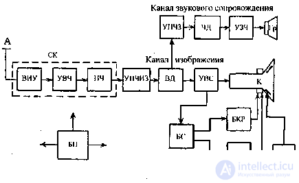
SK selector television channels, consisting of an input selective device (VIA), high frequency amplifier (UHF) and frequency converter (IF);
VD video detector;
UVS-video signal amplifier;
BS block sync;
БКР, ББР - block of personnel and line scanning;
K - kinescope;
BH-frequency detector;
UZCH audio amplifier,
Gr - loudspeaker,
BB (BBB) high voltage rectifier.
FID clock selector
GKR frame scanning generator
GSR horizontal line generator
A television antenna (A) for receiving radio signals of certain channels must have a corresponding bandwidth, and its resistance is matched in the same way as the resistance of the input circuit of the receiver with the wave impedance of the feeder1.
In the VIA there is a selection of the selected television signal. The selected signal has a small voltage, so it must be strengthened. To do this, use UHF. From here, the signal arrives at the IF, which consists of two parts — the local oscillator and the mixer. The local oscillator has the same number of oscillatory circuits as in the WC. From the local oscillator, the signal goes to the mixer, and signals from the VIS are also sent here. In the mixer, the carrier frequency of the image f and the carrier frequency of the soundtrack
interact with the local oscillator frequency f, which results in oscillations of the intermediate image frequency i and sound f:

Thus, two intermediate frequencies are generated in the transducer — image and sound, with the intermediate image frequency 6.5 MHz higher than the intermediate sound frequency. When tuning the TV to any channel, the intermediate frequencies are always the same and equal to 38.0 and 31.5 MHz respectively. These are high-frequency modulated oscillations, which fully preserve the sleeping shape, but having lower frequencies of the received signals.
For more precise tuning to the station, the frequency of the local oscillator can be changed within small limits by adjusting the capacity of its oscillating circuits. Most televisions have an automatic local oscillator frequency (APCG) tuning.
From the IC, the intermediate frequencies arrive at the UCPT, in which their main amplification occurs. The amplified intermediate frequencies from the UCPHP are directed to a video detector, which performs two functions: selects the video signal and converts the intermediate sound frequency to a new intermediate frequency — the second intermediate sound frequency. It is formed as a result of the interaction of intermediate frequencies of the image and sound and is equal to 6.5 MHz; 38.0 MHz — 31.5 MHz = 6.5 MHz. In other words, for the sound signal, the video detector performs the functions of a frequency converter (the local frequency of the image serves as the local oscillator voltage). The video signal from the VD video detector is fed to the DPS and, after amplification, to the kinescope modulator. The second intermediate frequency of sound from the VD arrives at the UPCS, where it is amplified. Then it goes to the BH, which highlights the sound component, which is amplified in the ASU and fed to Gy.
Through all the blocks without a change passes the synchronization signal allocated from the block UVS using the block synchronization BS. This unit divides the sync pulses into personnel and lower case, controlling the work (BKR) and (BSR), from which they come to the deflecting system. High-voltage horizontal reversing pulses are applied to a high-voltage explosive rectifier, at the output
which produces a constant high voltage to power the second anode of the kinescope.
All the necessary currents blocks the TV provides power supply BP.
The composition of the full video signal at the output of the DPS contains synchronization pulses transmitted by the telecenter in rows and frames, ensuring the electron beam moves across the screen of the kinescope synchronously and in phase with the beam moving along the target of the transmitting tube on the telecentre during the return stroke of the lowercase and personnel sweep. To select the sync pulses from the full television signal, the FID sync pulse selector is used. Selection of synchronization pulses occurs due to the fact that the amplitude of these pulses is always greater than the level of the image signal corresponding to the blackest elements (the level of sync pulses is “blacker than black”). The FID mode is chosen such that it is always locked and unlocked only by synchronization pulses due to the fact that their amplitude is greater than the voltage of the video signal. The sync pulse selector also includes the elements of the separation of sync mixtures into sync pulses of rows and frame sync pulses. For the separation, the difference between the durations of the synchronizing pulses is used: the duration of the horizontal sync pulses is significantly less than the duration of the frame pulses. Therefore, after differentiating the synchromesh, pulses are allocated to synchronize the horizontal scanning of the TV, and after integrating the synchromesh, the synchronization pulses of the vertical scanning are extracted.
Frame sync pulses from the FID output are fed to the master oscillator of the GKR frame scan, which controls the GKR output stage, which produces sawtooth voltage. To obtain a linear vertical sweep, the output stage of the HRS creates a ramp current in time-varying in the personnel deflection coils of the deflection system of the operating system. Connecting the output GKR with personnel deflecting coils OS is carried out either by using the output frame transformer, which ensures the coordination of large output impedance of the lamp cascade with a small input resistance deflecting coils, or directly (without transformer) in semiconductor circuit GKR, the output resistance of which is much less. The deflecting system is put on the neck of the kinescope and controls the electron beam, affecting its deflection by the magnetic field of its coils.
The horizontal sync pulses from the FID output are fed to the automatic frequency control and horizontal scanning phase of the AFCHF, where they are compared in time with the horizontal sweep of the horizontal flip-flop from the output of the horizontal sweep generator. When these and other pulses coincide in time, the output voltage of the AFChIF becomes zero, otherwise a control DC voltage is produced, the level of which is proportional to the deviation of the output GSR pulses from the synchronizing ones, and the polarity depends on whether the pulses come from the GSR output earlier or later sync. The APC & A scheme has a high inertia, due to which its operation is not affected by the impulse noise coming along with the signal. The control voltage from the output of the AFCS system is fed to the horizontal scanning master oscillator, and under its influence the frequency of the developed scanning voltage changes. GSR contains an output stage, from where the deflection current is fed to the horizontal deflection coils of the OS.
Here, new units already listed above have been added to the scheme: a remote control card, a video processor with a chroma decoder, a teletext decoder, a DVD player, a USB media player can be added.

Here the scheme has changed even more since digital signal processing is mainly used. For example, COFDM - orthogonal frequency division coding processing with coding, widely used in television. The abbreviation LVDS is a method of transmitting signals to the matrix. Inverter - generates voltage for the backlight (or LEDs in LCD and OLED TVs) and adjusts it. Flash memory (ROM) is the TV's own memory that stores information about your settings, built-in functions, and receiver control. RAM - RAM, is involved in data processing when running TV. With the rest, I think so clear.
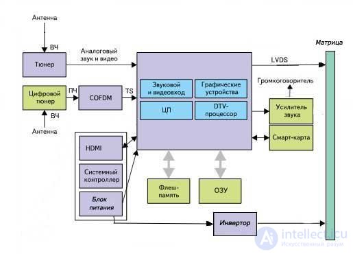
LCD block diagram
Something similar will be on the structural diagram of the plasma TV.
The conceptual scheme for the division into functional blocks applies the reference designations of the elements of capacitors, resistors, and so on. For example, R805, C806, will refer to the power supply, and R705 and C706 to lowercase. Appropriate designations will be present on the chassis board of the TV.
To fully diagnose a faulty TV, a visual inspection is required, both outside and inside the device. If the malfunction is not complicated, there is an opportunity for self-repair. For example, a faulty remote from the TV can be quite easily disassembled and cleaned, as well as changing the dead batteries. It is also easy to replace the faulty wire, if of course it was precisely possible to understand that the problem lies in it. In modern TV internal parts and components are often replaced completely.
Internal knots and details of the TV are subject to breakages, most often malfunction can be found:
Disabling the HDMI input may incorrectly connect, since the connection of external devices should occur only in the off state.If connections occurred during operation, a closure could occur, which was the cause of the failure. Repair / replacement of this connector requires certain skills and qualifications, so it is best to contact the experts. Before calling the wizard, it is recommended to check the correctness of the cable connection to HDMI, whether there are any contacts, check the settings and the sequence of connecting devices. If your TV is not one HDMI port, check everything.
If your TV does not have an image, but there is a sound, the possible perpetrators of this malfunction - an inverter, power supply, lamp or matrix. With a faulty power supply, the TV not only has no image, but there is no reaction to the remote control or buttons on the TV. Also, a dark screen may indicate damage to the backlight module or backlight lamps. A new TV that has just been connected may not display an image due to improper connection or a faulty connecting cable. Before calling the wizard for repair, be sure to check the settings of your TV, because perhaps the problem of the lack of an image is associated with them.
Отсутствие какого либо цвета в изображении на экране телевизора сообщает о неисправности модуля цветности, однако могут быть и другие причины например - неисправность видеоусилителя, элементов на плате модуля, микросхемы. В кинескопных телевизорах отсутствие красного цвета говорит о неисправности кинескопа или канала цветности. При отсутствии зеленого цвета, возможной причиной может быть, проблема с контактами на плате. Цветные пятна на кинескопе телевизора говорят о неисправности системы его размагничивания, если рядом нет предметов спровоцировавших это явление (их можно убрать и все вернется в норму), то кинескоп подлежит замене.
Причины помех на экране телевизора бывают как внутренние, так и внешние. Внутренние неисправности блоков телевизора может диагностировать и устранить только специалист, а вот с внешними можно попытаться побороться самостоятельно. В первую очередь рекомендуется проверить антенный кабель и его соединения, также позвонить поставщику тв услуг и уточнить не ведутся ли профилактические работы, обратить внимание какие электроприборы работают в квартире на момент появления помех, ведь причина может быть и в них.
Если ваш телевизор производит автоматическую настройку каналов, но не сохраняет их, то проблема достаточно серьезная, возможно неисправны микросхемы памяти телевизора. Такую поломку может исправить только опытный мастер, диагностировать и заменить неисправные детали. Также бывает, что каналы настраиваются только в ручную, автоматическая настройка не работает, причина этого неисправность микроконтроллера. В этом случае вы можете и дальше пользоваться ручной настройкой, если для вас это не критично.
Звук в телевизоре производят встроенные динамики, если нет звука у телевизора то в первую очередь проверяют на исправность динамики, а также шлейф подключения динамиков. Если динамики и их соединение исправны, то неисправность, скорее всего, в системной плате. Не стоит исключать и настройки телевизора, возможно их необходимо изменить и, именно, они ответственны за отсутствие звука у вашего тв.
Полосы на экране телевизора говорят о серьезных неисправностях. Самая простая неисправность в данном случае - это проблемы с контактом шлейфа. Возможно неисправен блок строчной или кадровой развертки. Также полосы на экране телевизора могут быть показателем неисправности матрицы. Для точной диагностики, рекомендуется пригласить опытного специалиста, который после осмотра скажет, что именно вызывает данную неисправность.
В случае, если ваш телевизор перестал включаться, провод и розетка исправны, то к данной неисправности могут быть причастны - блок питания инвертора или блоки строчной и кадровой развертки. Последовательная диагностика позволит выявить неисправность и произвести ремонт.
Неисправности плазменных телевизоров напрямую связана с их конструкцией и принципом работы. Цветовоспроизведение экрана плазменного телевизора происходит за счет множества капсул заполненных инертным газом. Поверхность каждой ячейки покрыта слоем люминофора, который окрашен в один из цветов - красный, зеленый или голубой. При поступлении электрического тока, газ в ячейках плазменного экрана меняет ионизированное состояние на плазму, и капсула начинает светить в соответствии с цветом покрытия.
Одна из частых неисправностей плазменных тв - это выгорание слоя люминофора. Для избежания таких проблем, рекомендуется не устанавливать плазменный телевизор туда, где экран может часто подвергаться воздействию прямых солнечных лучей. Также экран плазменного телевизора негативно переносит долгое статичное изображение, постоянный показ статичной картинки может привести к выгоранию некоторых пикселей.
Плазменные телевизоры подвержены сбоям программного обеспечения, решением такой проблемы является переустановка ПО.
Полное или частичное отсутствие изображения, неправильное воспроизведение цветов - могут иметь различные причины. Довольно часто данная неисправность разрешается с помощью настройки тюнера или усилителя сигнала. Более серьезны неисправности устраняются путем замены или ремонта микросхем, контролеров, ресиверов, плат и других блоков и узлов телевизора.
Одной из весьма частых неисправностей, является поломка пульта дистанционного управления. Неисправный пульт просто заменяется на новый. Однако нерабочие состояние пульта дистанционного управления может быть связано с сбоем настрое пульта, в таком случае, необходимо перепрограммировать контролер и осуществить настройку блока управления внутри плазменной панели.
Very often, serious malfunctions of a plasma TV appear due to overheating. And the primary cause of overheating is dust, which is deposited on the cooling system, preventing it from working fully. You can simply carry out preventive cleaning with a certain regularity and, of course, carry out immediate cleaning if you have heard changes in the sound of the cooling system. Since the cost of repairs after the effects of overheating can be considerable.
The LCD display of the TV consists of a backlit LCD matrix, the backlight can be a lamp or LCD. The LCD matrix in turn consists of pixels. The presence of broken pixels, even in the new TV is a valid defect. The international standard allows 4 classes of quality LCD displays and only the highest class does not allow the presence of dead pixels.
Такая неисправность жк телевизора как мигание экрана может быть вызвана поломкой лампы подсветки или неисправностью ее системы охлаждения. Полосы на экране жк телевизора или отсутствие цвета говорит о неисправностях в: видеопроцессоре, трансформаторе или видеоусилителе.
Важной деталью жк телевизора является блок питания, многие неисправности телевизора происходят из за его поломок. Нестабильное напряжение в электросети очень вредно для блока питания, чтобы избежать и предупредить многие неисправности жк телевизора, рекомендуется установить стабилизатор напряжения.
Узкая вертикальная полоса на экране жк телевизора сигнализирует о неисправности строя трансформатора строчной развертки, ремонт данной поломки может выполнить только специалист обладающий специальными навыками и знаниями.
Отсутствие сигнала и снег на экране являются симптомами неисправности антенны либо антенного кабеля, также при таких симптомах может быть неисправен тюнер. Те же симптомы можно обнаружить при отсутствии радиоканала или контакта на входе приема сигнала.
Производить поиск неисправностей телевизора лучше всего последовательно проверяя его основные узлы и детали.
В первую очередь нужно начать с визуального осмотра и очистки от пыли внутренних частей телевизора. После очистки мягкой кистью и пылесосом может стать видно вздувшиеся или разорвавшиеся конденсаторы, обгоревшие резисторы, прогоревшие микросхемы, после очистки внутренней поверхности кинескопа от пыли по молочно-белому цвету, вместо прозрачной поверхности, может быть диагностирована потеря вакуума.
Часто при визуальном осмотре не удается увидеть явных причин неисправности телевизора, в таком случае поиск неисправностей следует начать с блока питания телевизора.
Проверка неисправности блока питания телевизора (проверка напряжения питания, напряжения нагрузки, целостности элементов первичной цепи блока питания и цепи обратной связи, которая служит для установки и стабилизации выходного напряжения, проверка электролитических конденсаторов, в случае высыхания их емкость существенно уменьшается, что ведет к некорректной работе схемы и повышению вторичных напряжений).
Проверка строчной развертки (проверка выходного каскада, проверка выходного транзистора строчной развертки, строчного трансформатора, проверка на пробой строчных отклоняющих катушек).
Проверка кадровой развертки (проверка питания задающего генератора и выходного каскада, проверка на пробой или обрыв выпрямительного диода, проверка микросхемы кадровой развертки, проверка на межвитковое замыкание в кадровых отклоняющих катушках).
Проверка цепи питания кинескопа (проверка напряжения накала, а при его наличии целостности нити накала кинескопа).
Проверка радиоканала, блока цветности, видеоусилителя (нет звука и изображения - проверка напряжения питания радиоканала, проверка тюнера и видеопроцессора, есть звук нет изображения - проверка видеоусилителя или блока цветности, есть изображение, нет звука - проверка видеопроцессора или усилителя низкой частоты).
Проверка блока управления (телевизор не включается - проверка наличия питания на процессоре и проверка работы тактового генератора, телевизор включается на пульт не реагирует - проверка пульта, проверка прохождения сигнала от фотоприемника до процессора, проверка процессора, телевизор не реагирует на кнопки - проверка кнопок, проверка подачи импульсов на шину управления, проверка исполнительных устройств, телевизор не настраивает каналы - проверка узла выбора поддиапазона, проверка транзисторов на процессоре, проверка процессора, проверка узла выработки напряжения настройки, телевизор не сохраняет настройки памяти - проверка обмена данными между процессором управления и микросхемой памяти по шинам CS, CLK, D1, DO, проверка микросхемы памяти)
В этом тексте были перечислены только некоторые неисправности телевизоров, большинство из которых, можно исправить только обладая специальными знаниями. Современные телевизоры становятся все более сложными и часто не подлежат непосредственно ремонту, неисправность устраняется путем замены той или иной детали, узла или блока.
Найти дефект гораздо сложнее, чем его устранить, особенно начинающему мастеру. Предложенная автором статьи универсальная методика позволит Вам быстро и эффективно провести диагностику современного телевизора.
C ЧЕГО НАЧАТЬ
При ремонте телевизионных приемников встречаются ситуации, когда телевизор не включается и не подает никаких признаков жизни. Это значительно затрудняет локализацию дефекта, особенно если учесть, что ремонтировать импортную технику часто приходится без принципиальных схем. Перед мастером встает задача выявить неисправность и устранить ее с наименьшими затратами времени и усилий. Для этого необходимо следовать определенной методике отыскания неисправностей.
Если мастерская или частный мастер дорожит своей репутацией, необходимо начинать с чистки аппарата. Вооружившись мягкой кистью и пылесосом, следует произвести чистку внутренней поверхности корпуса, поверхности кинескопа и платы телевизионного приемника. После тщательной очистки производят внешний осмотр платы и элементов на ней. Иногда можно сразу определить место неисправности по вздувшимся или разорвавшимся конденсаторам, по обгоревшим резисторам или по прогоревшим насквозь транзисторам и микросхемам. Бывает, что после очистки кинескопа от пыли вместо прозрачной колбы мы видим молочно-белую внутреннюю поверхность (потеря вакуума).
Значительно чаще визуальный осмотр не выявляет внешних признаков неисправных деталей. И тут возникает вопрос - с чего начать?
БЛОК ПИТАНИЯ
It is most advisable to start the repair with a test of the power supply. To do this, turn off the load (horizontal output stage) and connect an incandescent lamp of 220 V, 60 ... 100 W instead.
Normally, line feed voltage is 110 ... 150 V depending on the size of the kinescope. After reviewing the secondary circuits, on the board next to the pulse transformer of the power supply we find the filter capacitor, which most often has a capacity of 47 ... 100 microfarads and an operating voltage of about 160 V. Next to the filter is the horizontal power supply rectifier. After the filter, the voltage goes to the output stage through a choke, a limiting resistor or a fuse, and sometimes the board simply has a jumper. Having unsoldered this element, we will disconnect the output stage of the power supply unit from the horizontal scanning stage. In parallel to the capacitor, we connect an incandescent lamp - a load simulator.
When you first turn on the key transistor of the power supply may fail due to malfunction of the binding elements. In order to prevent this from happening, it is better to turn on the power supply unit through another incandescent lamp with a power of 100 ... 150 W, which is used as a fuse and turned on instead of a soldered component. If there are defective elements in the circuit and the current consumption will be high, the lamp will light up and all the voltage will drop on it. In such a situation, it is necessary, first of all, to check the input circuits, the network rectifier, the filter capacitor and the high-power transistor of the power supply. If, when turned on, the lamp lights up and immediately goes out or starts to glow dimly, then we can assume that the power supply is healthy, and it is better to make further adjustments without the lamp.
Turning on the power supply, measure the voltage at the load. Take a close look at the board to see if there is an output voltage adjustment resistor around the power supply unit. Usually next to it is an inscription indicating the magnitude of the voltage (110 ... 150 V).
If there are no such elements on the board, pay attention to the presence of control points. Sometimes the value of the supply voltage is indicated next to the primary winding of the line transformer. If the kinescope diagonal is 20 ... 21 ", the voltage should be in the range of 110 ... 130 V, and with a kinescope size of 25 ... 29", the supply voltage range is usually 130 ... 150 V.
If the supply voltage is higher than the specified values, it is necessary to check the integrity of the elements of the primary power supply circuit and the feedback circuit, which serves to set and stabilize the output voltage. You should also check the electrolytic capacitors. When dried, their capacity is significantly reduced, which leads to a malfunction of the circuit and an increase in secondary stresses.
For example, on an Akai CT2107D TV, when the electrolytic capacitor C911 (47 μF, 50 V) dries out, the voltage in the secondary circuit instead of 115 V may increase to 210 V.
If the voltages are low, check the secondary circuits for short circuits or large leaks, the integrity of the protective diodes R2K, R2M in the horizontal power supply circuit and protective diodes of 33 V in the power supply circuit of the vertical scan.
For example, on a Gold Star CKT 2190 TV, when a failed line filter power capacitor 33 μF, 160 V, which has a high leakage current, the output voltage instead of 115V was about 30 V.
On the Funai TV-2000A MK7, the R2M protective diode was pierced, which triggered the protection, and the TV did not turn on; In Funai TV-1400 MK10, the breakdown of a 33-volt protective diode in the vertical power supply circuit also led to the protection being triggered.
LINE SCROLL
Having dealt with the power supply and making sure that it is working, we restore the connection in the horizontal power supply circuit by removing the lamp that was used instead of the load.
To first turn on the TV, it is desirable to install an incandescent lamp used instead of a fuse.
With a good horizontal output stage, when turned on, the lamp will turn on for a few seconds and turn off or glow dimly.
If the lamp flashes when it is turned on and continues to burn, you need to make sure that the horizontal output transistor is working. If the transistor is normal and there is no high voltage, make sure that there are control pulses on the base of the horizontal output transistor. If there are pulses and all voltages are normal, it can be assumed that the line transformer is faulty.
Sometimes this is immediately understandable by the strong heating of the latter, but it is very difficult to tell if the TDX is working properly. In order to determine this accurately, you can use the following method. We send rectangular pulses with a frequency of 1 ... 10 kHz of small amplitude to the collector winding of the transformer (you can use the output signal of the oscilloscope calibration]. We also connect the input of the oscilloscope there.
With a good transformer, the maximum amplitude of the received differentiated pulses should not be less than the amplitude of the original rectangular pulses.
If TDKS has short-circuited coils, we will see short differentiated pulses with an amplitude of two or more times smaller than the original rectangular ones. This method can also determine the failure of transformers of the network pulse power supply units.
The method works without watering the transformer (of course, you need to make sure that there is no short circuit in the secondary strapping circuits).
Another horizontal scan malfunction, in which the power supply does not turn on and the lamp turned on instead of the fuse, glows brightly - a breakdown of the horizontal deflection coils. This fault can be identified by disconnecting the coils. If after that the TV turned on normally, then the deflecting system [OS] is probably faulty. To verify this, replace the deflecting system with a known-good one. TV at the same time you need to turn on for a very short time to avoid burning through the kinescope. Replacing a deflection system is not difficult. It is better to use the OS from a similar kinescope with a diagonal of the same size.
The author had to install in the Funai 2000 MKZ TV a deflecting system from a Philips 21-inch TV. After installing the new OS on the TV, it is necessary to adjust the convergence of the beams using a television signal generator.
PERSONNEL SCAN
If the line scan is normal, then at least the horizontal bar should be lit on the screen, and if the frame scan is healthy, the full raster should be on. If there is no raster and a bright horizontal bar is visible on the screen, the accelerating voltage [Screen] on the TDX should be adjusted to reduce the brightness of the screen. This is necessary in order not to burn the phosphor tube, and only after that you should look for a fault in the personnel scan.
Diagnostics in the frame scanning unit should begin with checking the power of the master oscillator and the output stage. Most often, the power is taken from the winding of a line transformer. The supply voltage of these stages is 24 ... 28 V. The voltage is supplied through a limiting resistor, which must be checked first. Frequent failures in the frame scan are breakdown or breakage of the rectifier diode and breakdown of the frame scan chip. Rarely, but still there is an inter-turn closure in personnel deflection coils.
If a deflecting system is suspected, it is better to check it by temporarily connecting a known good coil. Control should be performed with an oscilloscope, observing the pulses directly on the frame coils.
KINESCOPE POWER SUPPLY CHAINS
It happens that the power supply and scanner are OK, and the TV screen is off. In this case, you need to check the voltage of the filament, and if it is present, the integrity of the filament of the kinescope.
In the author's practice, there were two cases when the filament winding of a line transformer was broken (Sony and Waltham TVs). Do not rush to change the line transformer. To begin with, it should be carefully discharged, cleaned of dust and carefully inspect the incandescent windings.
Sometimes a cliff is located near the outlet under a layer of epoxy. Hot soldering iron gently remove part of the resin and, if a break is found, remove it, after which it is desirable to fill the repair site with epoxy resin.
If the break could not be found, you can wind the filament winding on the core of the same transformer. The number of turns is chosen empirically (usually it is 3 ... 5 turns, MGTF wire 0.14]. The ends of the winding can be fixed with glue or mastic.
RADIOKANAL, BLOCK OF COLOR, VIDEO AMPLIFIER
If the sweep is normal, the screen is lit, and there is no image, you can identify the faulty unit by the following features.
In the absence of sound and image malfunction must be sought in the radio channel (tuner and video processor).
If there is sound and no image is present, the fault should be sought in the video amplifier or color unit.
If there is an image and there is no sound, the video processor or low-frequency amplifier is most likely faulty.
After checking the supply voltage of the radio channel, you need to send video and audio signals through a low-frequency input (you can use a television signal generator or a regular VCR).
If there is no picture or sound, you should use the oscilloscope to trace the signal from the source from which the signal was sent to the cathodes of the kinescope or, if the sound channel is faulty, to the loudspeakers and, if necessary, replace the faulty element.
If after sending a signal to the low-frequency input, the image and sound appeared, then the fault should be sought in the previous stages.
When checking the video processor, the IF signal must be sent to the input of the FSS from the generator or from the tuner output of another TV.
If the image and sound did not appear, check the path of the signal using an oscilloscope and, if necessary, change the video processor (when replacing the chip, it is better to solder the socket immediately).
If there is an image and sound, then the fault should be sought in the tuner or in its harness. First of all, you need to check whether the power is supplied to the tuner.
Check the serviceability of the key transistors through which the voltage comes to the tuner when switching bands. Check whether the signal from the control processor is sent to the bases of these transistors, check the magnitude and range of the setting voltage, which should vary between 0 ... 31 V.
When diagnosing faults tuner need to send a signal from the antenna to the mixer, bypassing the stages of the RF amplifier. For this it is convenient to use the probe, which can be made from a disposable syringe with a remote piston. At the top of the syringe, an antenna socket should be installed and through the 470 pF capacitor connect the central contact with the needle. We take the earth by ordinary wire; for convenience, it is better to solder the crocodile clip to the earth wire. The probe is connected to the antenna plug and give a signal to the tuner cascades.
With the help of such a probe, it was possible to identify a fault in the tuner of the Grundig T55-640 OIRT TV. In this unit, the first UHF cascade was defective. The fault is eliminated by sending a signal through a 10 pF capacitor directly from the antenna jack, bypassing the first transistor to the next tuner stage. The image quality and sensitivity of the TV after such alterations remained quite high and did not even affect the operation of teletext.
CONTROL BLOCK
Especially it is necessary to dwell on the diagnosis of the TV control unit.
When it is repaired, it is desirable to use a circuit or reference data on the control processor. If you could not find such data, you can try to download them from the site of the manufacturer of these components via the Internet.
A fault in the unit may manifest itself as follows: the TV does not turn on, the TV does not respond to signals from the remote control or the control buttons on the front panel; , no indication of control parameters.
If the TV does not turn on, first we check the availability of power on the processor and the operation of the clock generator. Then you need to determine whether the signal from the control processor to the switching circuit. To do this, find out the principle of turning on the TV.
The television can be turned on using a control signal that triggers the power supply, or by unblocking the passage of horizontal trigger pulses from the master oscillator to the horizontal scanner.
It should be noted that on the control processor, the turn-on signal is indicated by either Power or Stand-by. If the signal comes from the processor, then the fault should be sought in the switching circuit, and if there is no signal, the processor will have to be changed.
If the TV turns on, but does not respond to signals from the remote, you need to first check the remote itself. You can check it on another TV of the same model.
To test the remotes, you can make a simple device consisting of a photodiode connected to the CP-50 connector. The device is connected to the oscilloscope, the sensitivity of the oscilloscope is set within 2 ... 5 mV. The remote control should be sent to the LED from a distance of 1 ... 5 cm. On an oscilloscope screen, when the remote control is intact, pulse packets will be visible. If there are no pulses, we diagnose the console.
We successively check the power, the state of the contact tracks and the state of the contact pads on the control buttons, the presence of pulses at the output of the console chip, the health of the transistor or transistors, and the health of the emitting LEDs.
Often, after the fall of the console, the quartz resonator fails. If necessary, we change the defective element or restore the contact pads and button covering (this can be done by applying graphite, for example, with a soft pencil, or by gluing metallized film on the buttons).
If the console is working, you need to trace the passage of the signal from the photodetector to the processor. If the signal reaches the processor, and nothing changes at its output, we can assume that the processor is faulty.
If the TV is not controlled from the buttons on the front panel, you must first check the health of the buttons themselves, and then trace the presence of polling pulses and feed them to the control bus.
If the TV is turned on from the console and the pulses arrive at the control bus, and the on-line adjustments do not work, you need to find out by what output the microprocessor controls this or that adjustment (volume, brightness, contrast, saturation). Next, check the paths of these adjustments, up to actuators.
The microprocessor generates control signals with a linearly varying duty cycle, and acting on actuators, these signals are converted to a linearly varying voltage.
If the signal arrives at the actuator, and the device doesn’t react to this signal, then the device must be repaired, and if there is no control signal, the control processor must be replaced.
If there are no settings for TV programs, we first check the subrange selection node. Usually, through buffers implemented on transistors, voltage is supplied from the processor to the tuner pins (0 or 12 V). Most often these transistors fail. But it happens that there are no subband switching signals from the processor. In this case, you need to change the processor.
Next, check the node generating voltage settings. The supply voltage usually comes from the secondary rectifier from the horizontal transformer and is 100 ... 130 V. From this voltage, 30 ... 31 V are formed with the help of a stabilizer.
The microprocessor controls the key that generates a setting voltage of 0 ... 31 V using a signal with a linearly varying duty cycle, which, after the filters, is converted into a linearly varying voltage.
The stabilizer of 30 ... 33 V most often fails. If the settings in the memory are not saved in the TV, it is necessary to check the data exchange between the control processor and the memory microcircuit via the CS, CLK, D1, DO buses at any setting. If there is an exchange, and the values of the parameters in the memory are not stored, replace the memory chip.
If there is no indication of control parameters in the TV, it is necessary to check in the display mode the presence of video impulses of service information on the control processor via R, G, B circuits and the luminance signal, as well as the passage of these signals through buffers to video amplifiers.
In this article we touched on a small part of the faults that are found in television receivers. But in any case, the method of finding them will help you correctly identify and eliminate the fault and will reduce the time spent on repairs.

Comments
To leave a comment
Diagnostics, maintenance and repair of electronic and radio equipment
Terms: Diagnostics, maintenance and repair of electronic and radio equipment