Lecture
Over the past 20 years, the hard disk is recognized as one of the most reliable components of a computer, but when it breaks down, the consequences can be tragic. Below is a block diagram of the hard drive troubleshooting.
Troubleshooting Hard Drives
Should all hard drives installed in the system unit be displayed in the BIOS settings? Most BIOS versions tell the user about the connected hard drives at boot time. Each BIOS motherboard should be able to identify the hard disk by brand, model, and specifications. Standard keys for accessing CMOS Setup after powering on DEL, ESC, F1 or F2 (in almost all laptops).
Hear the hard drive is gaining momentum? If you don’t hear anything at all when you turn on the power, you should start by troubleshooting the power supply. If you do not hear the disk spinning, you should make sure that the power cables are well installed, this is more true for IDE connectors on older ATA hard drives than on new sata power connectors. If the hard disk is hard to hear, you can try to pull the HDD out of the case and hold it in your hand during power up. If the disk rotates, you will feel its vibrations. But be extremely careful, there is a chance to drop it, especially scary if the hard drive falls during operation. To test the hard drive is convenient to use special adapters USB-IDE and USB-SATA.
Further, the diagnostic block diagram offers two ways:
old ATA drive, also known as IDE or PATA (for Parallel ATA)
new SATA (Serial ATA) drive.
SATA breaks much less frequently, data cables rarely cause problems, and are easier to install, although some SATA hard drives support both old and new power connectors. An IDE or ATA drive has a clear feature in the presence of a loop that can support two drives; for this purpose, jumpers are supplied with them. With the help of jumpers on the disk, the Master disk is installed for installation by the host and the Slave, or to make a choice according to the connection via loops (CS).
The first SATA hard drives worked at a speed of 1.5 Gb / s, this period was known as SATA 1. You probably think that it was not a big jump compared to the old IDE drives, but the IDE interface speed was measured in MB / s (note , byte, not bit). SATA 2 generations support 3.0 Gb / s, and the latest release, SATA 3, supports 6.0 Gb / s. Note that high speed is achieved by transferring data from the cache to disk, the rotation speed is inferior to "electronics". If you connect a SATA 2 or SATA 3 hard drive to an old motherboard, and it does not work properly, check for compatibility, study the configuration with jumpers to make it work at lower speeds equal to SATA 1.
It is much more pleasant to work with SATA hard drives than with outdated IDEs. For example, because of the special data cable, which eliminates all the confusion with setting jumpers, and besides, sata cables are more reliable than old IDE cables that were broken with frequent use. If your SATA drive is unwound, but the CMOS setup program does not detect it, then it is possible that you have that rare bad data cable and it does not establish a connection on the motherboard correctly. Usually this applies to cables without latches. If you know that the SATA cable is working properly, as it works on a different system board, try connecting to a different SATA port. If this is the only SATA hard drive in the system, and your motherboard supports SATA RAID and standalone SATA ports, use a separate port.
Have you connected two IDE hard drives to a wide cable with three connectors: one for the motherboard in the IDE port and one for each drive? If the cable goes directly, you need to set the jumper on the boot disk to the “Master” position, and on the second disk “Slave”. If this is an 80-wire cable with three connectors or an old 40-wire cable connected between two hard drives, it will support “Cable Select”, then you can install a jumper on both drives - CS, the position often goes by default.
Some computers are still assembled with old IDE drives, in Cable Select (CS) mode, where a 28-pin cable is installed as a Master or Slave. The 80-pin new Ultra DMA cables began shipping with new motherboards about fifteen years ago, and began to use color-coded connectors. Blue goes to the motherboard, gray goes to the Slave (in the middle of the cable) and black goes to the Master IDE drive at the end of the cable. It will always be the boot disk on the primary controller.
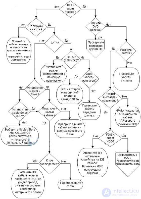
If after setting the Master / Slave BIOS modes the hard disks are not visible, check the power supply of the Molex 4 × 1 hard disk. It can take a lot of power to pull out the old power connector, the main thing here is not to use foreign objects to push if your fingers
Typical causes of malfunction of the hardware HDD can be divided into the following groups:
Malfunctions due to natural aging HDDs
With proper operation in compliance with all technical requirements in a high-quality storage drive, a process of natural aging is observed. Magnetic disks are most affected.
First, over time, the magnetization of minimal informational prints weakens, and those sections of disks that were previously read without problems begin to be read not from the first time or with errors.
Secondly, the aging of the magnetic layer of the disks.
Thirdly, scratches, chips, cracks, etc. appear on the plates. All this leads to the appearance of damaged sectors.
The process of normal aging of disks is quite long and usually stretches for 3 ... 5 years.
It should be noted that for NZhMD the most favorable is the continuous mode of operation, and not start / stop. Therefore, for a long time, drives serve in constantly working servers located in a special room or rack where normal climatic conditions are maintained.
Malfunctions due to incorrect operation
The most common cause of HDD failures are the main destructive factors of which are:
An important temperature indicator is the rate of temperature change, which should not exceed 20 ° C / hour in working condition and 30 ° C / hour in non-working. Speeding up the warm-up rate is very dangerous for drive mechanics and is called thermal shock.
Mechanical impacts on the HDA are detrimental to the precision mechanical parts of the drive. The impact on the HDA causes vibrations of the heads, which produce a series of blows on the surface of the disks, which inevitably leads to mechanical damage to the plates and heads.
A serious danger to the electronic part of HDD may be a poor-quality power supply unit of a personal computer. Supply voltages should be within +5 V ± 5% and +12 V ± 10% with a permissible ripple amplitude of 100 mV and 200 mV, respectively.
Design faults
Recently, the quality of HDD has decreased, as evidenced by a significant reduction in the warranty period of operation by the main manufacturers.
Poor contact in the needle connector connecting the electronics board and the preamplifier chip on the head unit. As a result of poor contact in the connector, incorrect information is recorded in the technological bytes of the sector, for example, in the CRC code field. This defect may result in damage to the service information, which the drive cannot restore during the next power up.
Poor chip soldering at the factory. Such defects appear after about one year of drive operation, when, during normal operation, the drive suddenly turns off and no longer starts (“freezes”), or starts “knocking” heads, which can lead to damage to the mechanics and / or service information.
Poor quality chips that fail during prolonged heating, not exceeding the permissible limits. Defect can be fixed by replacing the chip.
Imperfect design of the hydrodynamic bearing, which leads to the appearance of particles of chips in the lubrication cavity and, as a result, the spindle motor is jammed.
Poor mounting of the disk on the spindle, resulting in the beating of the disk is constantly increasing and causes the destruction of the bearing in the spindle motor; there is noise when the drive is working, and after a while - defective sectors, because due to the beating of the disk, the “long” tracks start to read poorly.
Poor-quality EEPROM chips (flash), which can lose the firmware stored in them due to charge leakage during heating. You can rewrite the ROM on a special programmer or in the technological mode of the drive.
Errors in drive management firmware. Manufacturers of drives do not publish information about the nature of errors and their consequences, but firmware updates are released quite regularly.
Symptoms of a malfunctioning disk First and most popular - when powering the drive with it is not
nothing happens, it is completely silent and does not even spin the spindle motor, or tries to do it, but does not gain the necessary momentum. A similar symptom may be present because the engine itself is jammed, or the heads fell on the disk and stuck to it (this happens on almost all modern disks, since the heads are perfectly polished and a diffusion effect occurs).
The second fault is the disk is spinning normally, but there is no parking of the heads - a characteristic quiet click. This rarely occurs, because head positioning control (servo system) and a three-phase generator for a spindle motor are often placed on a single chip, and if it fails, then usually all at once or unparking does not occur because the positioning coil on the head unit has broken.
The third fault is the disk is recalibrated normally when turned on power and does not emit extraneous sounds, but it is not defined in the BIOS, and the model name does not match the one written on the disc itself, or the name contains incomprehensible characters. In this case, very often the main interface chip on the electronics board is faulty. It is categorically not recommended to write to such a drive, since due to a data bus failure, data on the disk may be damaged.
The fourth fault is associated with a chip defect, which degrade from constant thermal expansions (temperature gradient). Fault manifests itself mainly with heating, i.e. for a while the disk works fine, and then it starts to gnash, knock, or stop the engine.
Hardware malfunctions of HDD IDE can be divided into the following groups:
Initial initialization failures result usually, to
complete inoperability drive.
In HDD with such a malfunction, very often even the spindle motor does not start (due to the fact that the control microprocessor does not issue a permit to start) or starts, then stops and starts again, etc., but in all cases the HDD does not generate a code 50Н in state register.
The main reasons why the drive microprocessor cannot perform initial initialization:
To isolate the fault: It is necessary to check:
Check the HDD reset circuit.
To do this, close and open the contacts 1 and 2 of the interface connector of the drive and the oscilloscope observe the passage of the "RESET" signal to the control microprocessor and the single-chip microcontroller.
If the control microprocessor receives clock pulses (or a quartz resonator connected to the microprocessor is excited) and the reset circuit works, then the microprocessor should work out the control program, as evidenced by the pulses at the ALE, RD, WR pins.
If a crystal oscillator connected directly to the microprocessor is not energized or there are no pulses at the ALE pin, then the drive microprocessor is most likely defective.

Figure 41 - Typical schematic diagram of the control spindle engine
Malfunction of the spindle motor control circuit.
If the spindle motor does not start when the drive is powered on, it is necessary to make sure that the HM unit is working by connecting a good electronics board.
If this is not possible, then check the resistance of the windings (phases) of the spindle motor, which should be approximately 2 ohms with respect to the average output, and then proceed to troubleshooting on the control board.
Sometimes the start of the spindle motor is not possible due to the magnetic heads sticking to the discs.
The criteria for starting a spindle motor are:
After turning on the power, the presence of motor start pulses with an amplitude of 11–12 V is monitored in three phases at terminals J14, J13, J12 (see Figure 40). If, for whatever phase of the voltage is less than 10 V, it is faulty m / s U3. With such a malfunction, the spindle motor cannot gain nominal revolutions and, as a result, the magnetic heads do not unpark.
The speed of rotation of the spindle motor can be monitored by INDEX pulses at the control point E35 (when the board is installed on the HDA). The INDEX pulse repetition period is ~ 12 ms, the INDEX pulse width is ~ 140 ns.
Controlled by the m / s U3 signal START. To start the spindle motor
START = 1, to stop START = 0.
Phase distribution is performed by the m / s U6 from its findings Fc1 - Fc6, the amplitude of the TTL control signals.
Feedback on the speed of rotation is carried out by reading the servo data (SERVO DATA).
In turn, the m / s of the U6 synchrocontroller generates a servo tag search signal (SERVO GATE) for ms. U11.
In the absence of special diagnostic equipment and software, the primary diagnostics of HDD can be made by connecting it to a separate power supply. The diagnostic device in this case is the ear of the operator.
When the power is turned on, the HDD performs: spinning the spindle motor, at which a rising sound is heard (4 ... 7 s), then a click follows when removing the heads from the parking zone and a very characteristic crackling sound that accompanies the recalibration process (1 ... 2 s) .
Performing recalibration indicates at least the health of the reset circuit, the clock generator, the microcontroller, the spindle motor control circuit and the positioning system, the data conversion reading channel, and also the health of the magnetic heads (at least one with which the initialization process occurs) and safety service information of the drive.
For further diagnostics, the HDD is connected to the Secondary IDE port, and in the BIOS, in the SetUp procedure, it is necessary to perform automatic detection of connected drives. In case of recognition of the model of the diagnosed HDD, the operating system is loaded and diagnostic software is launched.
The simplest diagnostics is an attempt to create a partition on the diagnosed drive (using the FDISK program) and the procedure of subsequent formatting (Format d: / u). If formatting (verification) reveals defects, information about them will be displayed on the computer screen. Detailed diagnostics of HDDs are carried out by special programs.

Comments
To leave a comment
Diagnostics, maintenance and repair of electronic and radio equipment
Terms: Diagnostics, maintenance and repair of electronic and radio equipment