Lecture
3.4.1.1. KEYBOARD DEVICE
The keyboard is designed to enter alphanumeric information and commands in the PC. The basis of the keyboard is the mat of contacts (keys). Keys can be executed
as:
The task of determining whether a key is pressed, forming its code (scan code) and transferring data to a PC is solved by a specialized micro-computer (keyboard controller). The block diagram of the controller is shown in Figure.
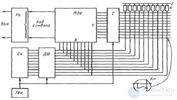
Figure 77 - Block diagram of the keyboard controller
The main elements of the controller are:
Output Register The keyboard communicates with the PC by a serial code.
The order of keyboard interaction with the PC is shown in Figure.
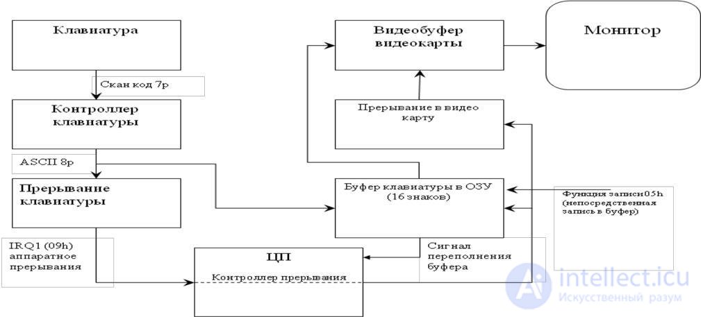
Figure 78 - The scheme of keyboard interaction with PC equipment
Each time the PC is turned on, the keyboard is tested by POST tests, the standard keyboard error codes for the POST procedure are displayed on the monitor screen and look like this (some BIOS types do not display keyboard error codes):
3xx - Keyboard Fault
301 - Keyboard reset failure or key sticking (XX 301, XX hexadecimal scan code)
302 - The keyboard switch on the system unit is locked
302 - User-defined keyboard test error 303 - Malfunction of the keyboard or motherboard; controller malfunction
304 - Malfunction of the keyboard or motherboard; high keyboard sync frequency
305 - Malfunction of power supply +5 V keyboard; PS / 2 keyboard fuse failed
341 - Keyboard malfunction
342 - Keyboard cable malfunction
343 - Malfunction of the cable or LED board of the keyboard
345 - Malfunction of the cable or LED board of the keyboard
346 - Keyboard Interface Cable Malfunction
347 - Malfunction of the cable or LED board of the keyboard
The mechanical mouse consists of:
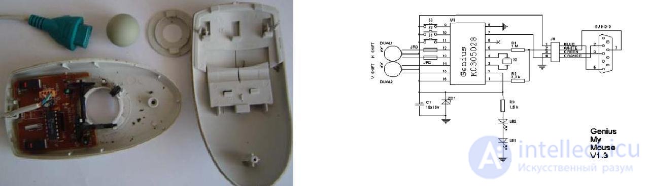
Figure 79 - Basic elements of a mechanical mouse Figure 80 - Schematic diagram of a mechanical mouse
The principle of the mouse is as follows: rolling the mouse on the table, we move the ball, the ball touches the rollers with disks, through the holes of which information flows to the photodetectors. The information of their photodetectors is processed in the control chip and transmitted to the PC via a serial interface. The mouse connects to the PC 4-wire cable.
Optical mouse
The main elements of an optical mouse are (Figure 2):
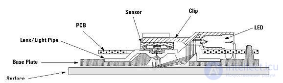
Figure 81 - Optical device
The principle of operation of an optical mouse is as follows: using an LED, and a system of lenses focusing its light, a surface area is highlighted under the mouse. The light reflected from this surface, in turn, is collected by another lens and hits the receiving sensor of the microcircuit - the image processing processor. This chip, in turn, takes pictures of the surface under the mouse at a high frequency (kHz). Based on the analysis of a series of consecutive images (representing a square matrix of pixels of different brightness), the integrated DSP processor calculates the resulting figures indicating the direction of movement of the mouse along the X and Y axes and transmits the results of its work to the outside through the serial port.
Keyboard cleaning
To maintain the keyboard in working condition, it must be cleaned. For prevention, it is recommended to clean it once a week (or at least once a month) with a vacuum cleaner. Instead of a vacuum cleaner you can use a miniature compressor to blow out dust and dirt. While cleaning with a compressor, hold the keyboard with the keys down. Once a year it is recommended to perform a full cleaning with a complete disassembly of the keyboard and washing in a soap solution of all the keys and the keyboard housing.
Keyboard replacement
It is often much easier and cheaper to replace the keyboard than to repair it, especially if the electronic "stuffing" or one of the keys is faulty. It is almost impossible to get spare parts, but even if they are, the procedure for replacing them is quite difficult.
Cleaning the mouse pad
The "slippage" of a mechanical mouse most often occurs due to the fact that dust and dirt have got inside the case. You can use a brush or cotton swabs to clean the mouse’s gut and remove the belt from the rollers with a match from the dirt. It is advisable not to touch the optical system: photo and LEDs. When they are displaced, the mouse may not work.
Very often during operation, both mechanical and optical mice, due to frequent bending, there is a break in the wires in the cable. As a rule, such a failure is indicated by the fact that the mouse is either working or not. The wires in the cable usually break off near the body of the mouse or near its connector. It is possible to determine the place of the break using a tester or by moving the cable with one hand and the mouse with the other.
If the cable near the mouse case is damaged, the cable is cut off at a distance of about 5 cm from the case. Solder the rest of the old cable and solder a new one.
It is more difficult if the cable is damaged near the connector as it is not collapsible. You can take a cable with a connector, from any mouse or search for a new connector.

Comments
To leave a comment
Diagnostics, maintenance and repair of electronic and radio equipment
Terms: Diagnostics, maintenance and repair of electronic and radio equipment