Lecture
The operation to adjust the monitor parameters must be performed after repair of the power supply unit, the synchro processor, lowercase, frame sweeps, high voltage and B + voltage generation circuits.
Before starting the adjustment, it is necessary to warm up the monitor. To do this, the monitor is connected to the network, the video signal is fed to the input (amplitude - 0.7 V, positive polarity; synchronization - TTL-level, any polarity, separate or composite signal), and let the monitor work for at least half an hour. During this time, its components will acquire an operating temperature, and further changes in parameters will be minimal. First of all, this refers to the cathode-ray tube itself and the deflecting system installed on it. When heated, these components change their geometrical dimensions, which directly affects the focusing and convergence of the rays. Therefore, monitors with a large diagonal (19-22 inches) before setting it makes sense to warm up a little longer.
Preliminary adjustments
1. High voltage adjustment.
A kilovoltmeter is connected between the common wire and the anode of the kinescope and the variable resistor VR551 sets a voltage equal to 26 ± 0.2 kV. On the TDKS (transformer), as a rule, there are two regulators, Focus and Screen. Screen Control - adjusts the anode voltage.
2. Voltage regulation B + (minimum size horizontally). They feed the monitor signal "grid". The on-screen adjustment of the H-Size sets the minimum horizontal size. Then the variable resistor VR601 set the horizontal size equal to 295 mm.
Basic adjustments
Adjusting the on-screen menu to set the brightness value of 50 units, and contrast - 100 units. They feed the monitor signal "grid". Then adjust the optimal geometry of the image using the OSD adjustments H.Size, V.size, H.phase, V. position, Pincushion, Trapezoid.
1. Focus adjustment.
First, the static focus adjuster (the bottom one on the T571 transformer) achieves optimal focusing of the image in the center of the screen. Focus adjustment is made by the Focus control located on the line transformer next to the Screen control. Before turning the knob, do not forget to mark its initial position with a marker. Then the dynamic focus control (upper on the transformer T571) achieve optimal focus at the edges and corners of the screen. If necessary, repeat the operation.
2. Reduction Reduction of rays, like focusing, happens
Static information is tuned by ring magnets on the neck of the kinescope. Dynamic mixing is carried out by the windings of the deflecting system.
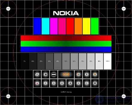
Reduction is also adjusted by tuning variable resistors located above the deflecting system, and, in some cases, by resistors located on the board installed at the end of the neck. Downed down looks like a frame of indefinite color on the contours of desktop shortcuts. If you turn on the test information in the Nokia monitor test, it will be seen that the crosshairs of different colors crawl over each other, forming an indefinite color in the “creeping” zone. In this case, you need to adjust the information so that this does not happen.
If there are no regulators on the board installed on the neck, you can adjust the reduction using ring magnets. As a rule, there are three pairs of such magnets on the neck of the tube. First of all, mark with a marker the position of all the magnets relative to the deflecting system with maximum accuracy, so that in case of failure everything could be at least returned to its original appearance. After that, it is necessary to cut the fixing mass with a sharp knife, which is usually fixed magnets relative to each other, otherwise it will not work out. Then you need to loosen the puck, a magnet package. This should be done very carefully, because with the use of force there is a high risk of cleaving the neck, after which the monitor can be safely thrown out. The washer, magnet, has a small, but nasty feature: as a rule, it has a reverse thread, that is, you need to twist it not counterclockwise, but vice versa. After loosening the magnets, turn on the information verification mode in the Nokia monitor test and neatly, using the “scientific tyke” method, find magnets deflecting the blue and red colors vertically and horizontally. In this way, by simple experiments, you can find the best option, in which all colors will be reduced exactly, without crawling on the next. This way you need to try to reduce the colors in the center of the screen, in the corners may remain unregulated areas by this method. To adjust them, it is necessary to use resistors located on top of the deflecting system coils, and inductance with a moving core located in the same place. If these bodies failed to reduce colors, then, alas, most likely it is impossible at all. However, most monitors are quite successfully configured in this way.
Then the dynamic focus control (upper on the transformer T571) achieve optimal focus at the edges and corners of the screen. If necessary, repeat the operation.
3. Adjusting the image geometry. Setting the image geometry should begin with the adjustment
sizes. Any test program has a special screen for setting this parameter. It shows perpendicular horizontal and vertical lines, on which one large central circle and several small corners are superimposed. First, through the monitor menu settings, you should ensure that the extreme lines of the test picture almost touch all edges of the screen. After that, measure with a ruler the diameter of the center circle in two perpendicular directions. Both values must be equal to within millimeter. Otherwise, you will have to resize vertically or horizontally until the circle becomes a circle, not an ellipse.
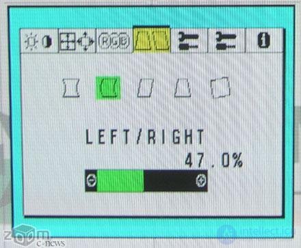
Along the vertical lines it is easy to notice another common image distortion - distortion. It is “pillow-shaped” and “barrel-shaped”. Such figurative terms, we hope, do not need comments. To compensate for distortion (and other distortions) in the monitor menu, there is a special item “geometry”, choosing which one should try to achieve a square image. It should immediately be said that it is very difficult to completely eliminate distortion. In its residual form, it is inherent in all monitors on cathode ray tubes, but our task is to make it minimal. The trapezium, parallelogram and image rotation distortions are less difficult to adjust. The presence and degree of such distortion is easily determined by the test image on the eye. As a reference line, you can use the frame of the screen, or attach a ruler along one of the sides of the image. To eliminate them, their own sub-items are provided in the geometry settings. Unfortunately, on some inexpensive monitors, manufacturers simplify the menu, and some items may not be there.
4. White balance adjustment.
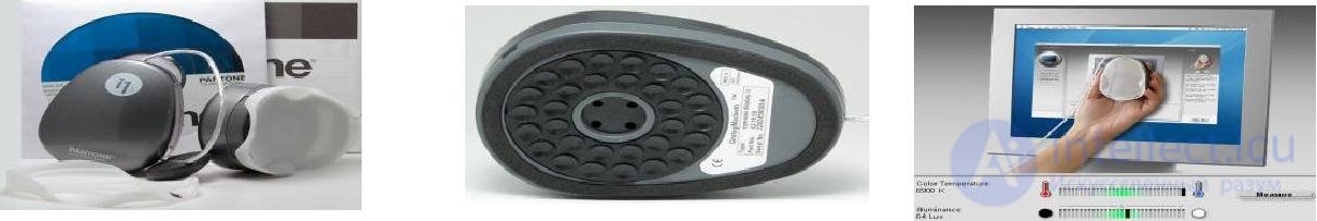
A black field signal is fed to the monitor input and a spectrum spectrum analyzer sensor is connected to the monitor screen. Select a color temperature of 9300 ° K from the on-screen menu. The brightness and contrast adjustments are set to the maximum level position, and the screen brightness value of 1 Ft / L is set using the Screen control on the T571 transformer. Then in the screen menu, select the parameters R-, G-, B-Bias and set the analyzer readings: x = 0,281; y = 0,311.
Serve on the input of the monitor signal "white field". Set the brightness adjustment to the 50 position, and the contrast to the maximum level position. Then in the on-screen menu, select the parameters R-, G-, B-Gain and set the analyzer readings: x = 0.281; y = 0.311. Using the contrast control set the value of the screen brightness 34
Ft / l.
After the adjustments are made, choose the color temperature from the on-screen menu at 6550 ° K and repeat the white balance adjustment with the only difference that the readings of the color analyzer should be as follows: x = 0.13; y = 0.329. Typical monitor failures and how to eliminate them will be published in the next issue of the journal.
Software for testing and configuring monitors
Microsoft Windows software
DOS Software
Monitor Adjustment Kits
Kits
they are intended to adjust (calibrate) the display in accordance with one of the accepted standards for displaying graphic files and create customized display profiles that will ensure the correct operation of the color management system.

Comments
To leave a comment
Diagnostics, maintenance and repair of electronic and radio equipment
Terms: Diagnostics, maintenance and repair of electronic and radio equipment