Lecture
The use case diagrams describe the functionality of the system or what the system should do. Chart development has the following objectives:
- define the general boundaries and context of the modeled subject area;
- to formulate general requirements for the functional behavior of the designed system;
- to develop the initial conceptual model of the system for its subsequent detailing in the form of logical and physical models;
- prepare the initial documentation for the interaction of the system developers with its customers and users.
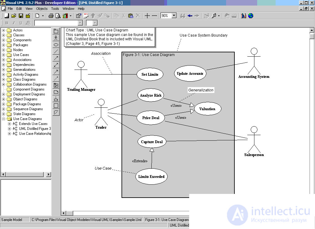
The essence of the use case diagram is as follows. The system being designed is represented as a set of entities or actors interacting with the system using use cases. In this case, an entity (actor) or actor is any entity that interacts with the system from the outside. It can be a person, a technical device, a program, or any other system that can serve as a source of influence on the simulated system as determined by the developer. The use case is used to describe the services that the system provides the actor. The use-case diagram can be supplemented with explanatory text that reveals the meaning or semantics of its constituent components.
A separate use case is indicated on the diagram by an ellipse , inside of which its short name or verb-shaped name with explanatory words is contained.
The purpose of a use case is to define a complete aspect or fragment of the behavior of an entity without disclosing its internal structure. As such an entity can act as a system or any element of the model that has its own behavior.
Each use case corresponds to a separate service that is provided by the entity being modeled at the request of the actor, that is, it determines the method of using this entity. The service, which is initialized at the request of the actor, is a complete indivisible sequence of actions. This means that after the system has finished processing the request, it must return to its original state in order to be ready for the next requests.
Use cases can be used to specify the external requirements for the designed system, as well as to specify the functional behavior of an existing system. The multitude of use cases in general should determine all possible aspects of the expected behavior of the system. In addition, use cases implicitly establish requirements that determine how actors should interact with the system in order to be able to work correctly with the services provided. For convenience, many use cases can be considered as a separate package.
Examples of use cases include the following actions: checking the status of a client’s current account, placing an order for purchasing goods, obtaining additional information about a client’s creditworthiness, displaying a graphical form on a monitor screen, and other actions.
An actor is any external entity in relation to the system being modeled, which interacts with the system and uses its functionality to achieve certain goals. In this case, the actors serve to designate a consistent set of roles that users can play in the process of interaction with the designed system. Each actor can be considered as a separate role for a specific use case. The standard graphic designation of the actor in the diagrams is the figure of a man , under which the name of the actor is recorded.
In some cases, an actor may be designated as a class rectangle with the keyword "actor" and the usual constituent elements of the class. The names of the actors should be written in capital letters and follow the recommendations of using names for types and classes of the model.
Examples of actors include a bank customer, bank clerk, shop assistant, sales manager, flight passenger, car driver, hotel administrator, cell phone, and other entities related to the conceptual model of the corresponding subject area.
Since, in general, an actor is always outside the system, its internal structure is not defined at all. For an actor, only how he is perceived by the system matters.
Actors interact with the system through messaging with use cases. A message is a request by an actor of a specific service system and the receipt of this service This interaction can be expressed through associations between individual actors and use cases or classes. In addition, interfaces can be associated with actors that define how other elements of the model interact with these actors.
Two or more actors can have common properties, that is, they can interact with the same set of use cases in the same way. Such a commonality of properties and behavior is represented as a relation of generalization with another, possibly abstract, actor who models the corresponding commonality of roles.
The interface is used to specify model parameters that are visible from the outside, without specifying their internal structure. In the UML language, the interface is a classifier and characterizes only a limited part of the behavior of the modeled entity. With reference to use case diagrams, interfaces define a set of operations that provide the necessary set of services for actors.
In the use case diagram, the interface is depicted as a small circle , next to which its name is recorded. The name can be a noun or a string of text. If the name is written in English, then it must begin with an uppercase letter I.
The graphical symbol of the individual interface is connected to the diagram by a solid line or a dotted line with an arrow with the use case that supports it. The solid line indicates that the use case associated with the interface should implement all the services necessary for it. The dotted line with an arrow means that the use case is intended to specify only the service that is required to implement this interface.
Thus, the interface separates the specification of system operations from their implementation and defines the general boundaries of the designed system.
Notes (notes) in the UML language are intended to include in the model arbitrary textual information directly related to the context of the project under development. Such information may include developer comments (for example, the date and version of the development of a diagram or its individual components), restrictions (for example, on the values of individual links or entity instances) and labeled values.
Graphically, notes are indicated by a rectangle with a curved upper right corner . Inside the rectangle contains the text of the notes.
If the note specifies the “constraint” keyword, then it is a constraint imposed on the corresponding model element.
Between the elements of the use case diagram, there may be different relationships that describe the interaction of the instances of the actors and use cases.
In UML, there are several standard types of relationships between actors and use cases:
- association (association);
- extensions (extend relationship);
- communication (generalization relationship);
- include relationship.
With reference to use case diagrams, an association specifies the semantic features of interaction between actors and use cases in the graphical model of the system, that is, this relationship determines what specific role an actor plays when interacting with an instance of a use case. In the use case diagram, the association relationship is indicated by a solid line between the actor and use case. This line may have a legend, such as name and frequency.
The multiplicity of the association is indicated next to the designation of the component of the diagram, which is a member of this association, and characterizes the number of instances of this component that can act as elements of this association. For diagrams of use cases, the multiplicity has a special designation in the form of one or more numbers and an asterisk.
For use case diagrams, the four most common forms of the multiplicity of an association relationship are the most common:
- non-negative integer (including 0). It is intended to indicate the multiplicity that is strictly fixed for the element of the corresponding association. In this case, the number of instances of actors or use cases that can act as elements of an association relationship is exactly the specified number;
- two non-negative integers separated by two dots. This record corresponds to the notation for a set or interval of integers, which is used in some programming languages to designate the boundaries of an array of elements. This record should be understood as a set of non-negative integers following in a sequentially increasing order;
- two characters separated by two dots. At the same time, the first one is a nonnegative integer number or 0, and the second is a special “*” symbol, which designates an arbitrary finite non-negative integer number, the value of which is unknown at the time of setting the corresponding association relation;
- the only character "*", which is the abbreviation of the entry interval "0 .. *".
If the multiplicity of the association relation is not specified, then, by default, a value of 1 is assumed.
An expansion relationship defines the relationship of instances of a particular use case with a more general variant, the properties of which are determined based on the way that the instances are co-aggregated. In a metamodel, the expansion relationship is directional and indicates that with respect to individual examples of a certain use case, the specific conditions defined for expanding this use case must be met. Thus, if there is an expansion relation from use option A to use option B , this means that the properties of the instance of use case B can be supplemented due to the presence of properties in the extended use case A.
The expansion ratio between use cases is indicated by a dotted line with an arrow (a dependency relationship option) directed from the use case that is an extension to the original use case. This line with an arrow is marked with the keyword "extend" (expands).
The attitude of the extension indicates the fact that one use case may add some additional behavior to its behavior, which is defined for another use case. This relationship includes some condition and links to extension points in the base use case. For an expansion to take place, a certain condition of the relationship must be satisfied. References to extension points define the places in the base use case where the appropriate extension should be placed when the condition is met.
One use case can be an extension for several basic options, as well as having several other options as your own extensions. The basic use case may additionally not depend on its extensions.
The semantics of an extension relationship is defined as follows. If an instance of a use case performs a certain sequence of actions that determines its behavior, and there is an extension point to an instance of another use case, which is the first of all the extension points of the original variant, then the condition of this relationship is checked. If the condition is met, the original sequence of actions is extended by including the actions of the instance of another use case. It should be noted that the condition of the expansion relationship is checked only once with the first reference to the extension point, and if it is satisfied, then all expanding use cases are inserted into the base case.
The generalization relation serves to indicate the fact that some use of A may be generalized to use B. In this case, option A will be a specialization of option B. In this case, B is called an ancestor or parent with respect to A , and variant A is a descendant with respect to use case B. A descendant inherits all the properties and behavior of its parent, and can also be supplemented with new properties and behavioral features. Graphically, this relationship is indicated by a solid line with an arrow in the shape of an empty triangle , which indicates the parent use case.
The relation of generalization between use cases is used in the case when it is necessary to note that the child use cases have all the attributes and peculiarities of the behavior of the parent options. In this case, child use cases are involved in all aspects of parent options. In turn, child variants may be endowed with new behavioral properties that are absent from parent use cases, as well as refine or modify behavior properties inherited from them.
In relation to this relationship, one use case may have several parent options. In this case, multiple inheritance of the properties and behavior of the ancestor relationship is realized. On the other hand, one use case may be an ancestor for several child variants, which corresponds to the taxonomic nature of the generalization relationship.
There may also be a generalization relationship between individual actors. This attitude is directed and indicates the fact of specialization of some actors relative to others. For example, the relation of generalization from actor A to actor B marks the fact that each copy of actor A is at the same time a copy of actor B and has all its properties. In this case, the actor B is the parent of the actor A , and the actor A is the descendant of the actor B. At the same time, the actor A has the ability to play the same many roles as the actor B. Graphically, this relationship is also indicated by a generalization arrow.
The inclusion relationship between two use cases indicates that some specified behavior for one use case is included as an integral component in the behavior sequence of another use case.
The semantics of this relationship is defined as follows. When an instance of the first use case reaches its point of inclusion in the sequence of behavior of an instance of a second use case, the instance of the first use case performs a sequence of actions that determine the behavior of the instance of the second use case, and then continues to perform actions of its behavior. It is assumed that even if an instance of the first use case may have several included instances of other options, the actions they perform must end by some point, after which the execution of the interrupted actions of the instance of the first use case should continue in accordance with the behavior specified for it.
One use case may be included in several other options, as well as include other options. The included use case may be independent of the base case in the sense that it provides it with some encapsulated behavior, the implementation details of which are hidden and can be redistributed among several included use cases. Moreover, the basic version can depend only on the results of the implementation of the behavior included in it, but not on the structure of the options included in it.
The inclusion ratio, directed from use case A to use case B , indicates that each instance of variant A includes the functional properties defined for option B. These properties specialize the behavior of the corresponding variant A in this diagram. Graphically, this relationship is indicated by a dotted line with an arrow , which is marked with the keyword "include" (includes).


Comments
To leave a comment
System modeling
Terms: System modeling