Lecture
types of diagrams, the sequential creation of which allows you to get a complete picture of the entire designed system and its individual components:
Use case diagram;
Deployment diagram;
Statechart diagram (state diagram);
Activity diagram;
Interaction diagram (interaction diagram);
Sequence diagram (sequence diagrams);
Collaboration diagram (collaboration diagrams);
Class diagram;
Component diagram.
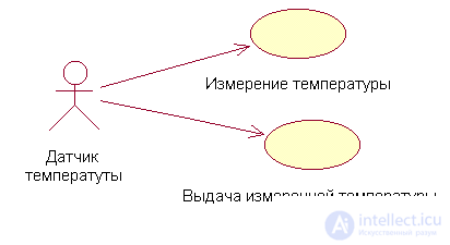
Use case diagram (case diagrams)
This type of charts allows you to create a list of operations that the system performs. Often, this type of diagram is called a function diagram, because based on a set of such diagrams, a list of system requirements is created and many functions performed by the system are determined.
Each such diagram or, as it is usually called, each Use case is a description of the behavior scenario followed by the actors (Actors).
This type of diagrams is used when describing business processes of an automated domain, determining the requirements for a future software system. Reflects the objects of both the system and the subject area and the tasks they perform.
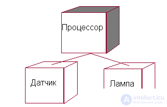
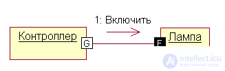
Deployment diagram
This type of diagrams is intended for analyzing the hardware of the system, that is, hardware, not programs. In direct translation from English, Deployment means “deployment,” but the term “topology” more accurately reflects the essence of this type of diagram.
For each model, only one such diagram is created that displays the processors (Processor), devices (Device) and their connections.
Usually this type of diagrams is used at the very beginning of the system design to analyze the hardware on which it will be used.
State Condition diagram
Each object of the system that has a certain behavior can be in certain states, go from state to state, performing certain actions in the process of implementing the scenario of the object's behavior. The behavior of most objects of real systems can be represented from the point of view of the theory of finite automata, that is, the behavior of an object is reflected in its states, and this type of diagrams makes it possible to reflect this graphically. Two types of diagrams are used for this: Statechart diagram (state diagram) and Activity diagram (activity diagram)
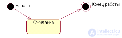
Statechart diagram (state diagram)
A statechart is used to display the states of objects in a system that have a complex pattern of behavior. This is one of two charts of the State Machine, which is accessed from one menu item.
Activity diagram
This is a further development of the state diagram. In fact, this type of diagram can also be used to reflect the state of the object being modeled, however, the main purpose of the Activitydiagram is to reflect the business processes of the object. This type of diagrams allows you to show not only the sequence of processes, but also branching and even synchronization of processes.
This type of diagrams allows you to design algorithms for the behavior of objects of any complexity, including those that can be used to create flowcharts.
Interaction diagram
This type of diagrams includes Sequence diagram diagrams (action sequence diagrams) and Collaboration diagram (collaboration diagrams). These diagrams make it possible from different points of view to consider the interaction of objects in the created system.
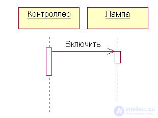
Sequence diagram (sequence diagrams)
The interaction of objects in the system occurs through the reception and transmission of messages by client objects and the processing of these messages by server objects. At the same time, in different situations the same objects can act both as clients and as servers.
This type of diagrams allows you to reflect the sequence of message transmission between objects.
This type of diagram does not focus on the specific interaction, the main focus is on the sequence of receiving / transmitting messages. In order to take a look at all the interrelationships of objects, use the Collaboration diagram.
Collaboration diagram (collaboration diagrams)
This type of diagrams allows you to describe the interaction of objects, abstracting from the sequence of message passing. This type of diagrams in a compact form reflects all received and transmitted messages of a particular object and the types of these messages.
Because the Sequence and Collaboration diagrams are different views on the same processes, Rational Rose allows you to create a Collaboration diagram from the Sequence diagrams and vice versa, and also automatically synchronizes these diagrams.
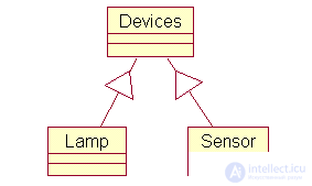
Class diagram
This type of diagrams allows you to create a logical representation of the system, on the basis of which the source code of the described classes is created.
Chart icons allow you to display a complex system hierarchy, class interconnections (Classes) and Interfaces. This type of diagrams is opposite in content to the Collaboration diagram, which displays system objects. Rational Rose allows you to create classes using this type of diagrams in various notations. In the notation proposed by G. Buch, which is called Booch, the classes are depicted as something fuzzy, like a cloud. Thus, G. Buch tries to show that a class is only a template according to which a specific object will be created in the future.
The OMT notation, in my opinion, is more strict.
And of course, Rational Rose allows you to create a class diagram in unified notation
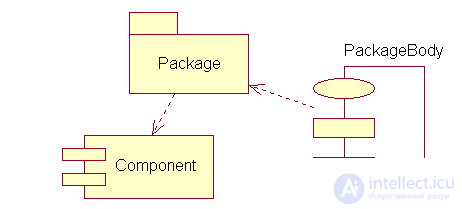
Component diagram
This type of diagrams is intended for the distribution of classes and objects by components during the physical design of the system. Often this type of diagrams is called module diagrams.
When designing large systems, it may turn out that the system should be decomposed into several hundreds or even thousands of components, and this type of diagrams makes it possible not to get lost in the abundance of modules and their connections.


Comments
To leave a comment
System modeling
Terms: System modeling