Lecture
Central to object-oriented programming is the development of a logical system model in the form of a class diagram. Class diagram (class diagram) is used to represent the static structure of the system model in the terminology of classes of object-oriented programming. The class diagram can reflect, in particular, various relationships between individual entities of the domain, such as objects and subsystems, as well as describe their internal structure and types of relationships.
A class diagram is a graph whose vertices are elements of the “classifier” type, connected by various types of structural relations. A class diagram can also contain interfaces, packages, relationships, and even individual instances, such as objects and connections.
Classes
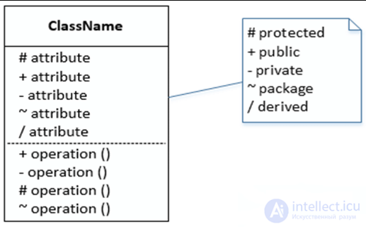
Class (class) in the UML language is used to designate a set of objects that have the same structure, behavior and relationships with objects of other classes. Graphically, the class is depicted as a rectangle, which can additionally be divided by horizontal lines into sections or sections. In these sections you can specify the class name, attributes (variables) and operations (methods).
A class name must be unique within a package, which is described by a set of class diagrams or a single diagram. It is indicated in the first upper section of the rectangle. In addition to the general rule for naming UML elements, the class name is written in the center of the name section in bold and must begin with a capital letter. It is recommended that nouns that are written without spaces be used as class names. Class names form a vocabulary domain.
In the first section of the class notation, there may be references to standard templates or abstract classes from which this class is derived and from which it inherits properties and methods. Additionally, this section may contain information about the developer of this class and the status of the development status, as well as record other general properties of this class that are related to other diagram classes or standard UML elements.
Class names can be such nouns as “Employee”, “Company,“ Manager ”,“ Client ”,“ Seller ”,“ Manager ”,“ Office ”and others that are directly related to the modeled subject area and functionality of the designed system.
A class may not have instances or objects. In this case, it is called the abstract class , and italics are used to designate its name. In UML, there is a general agreement that any text relating to an abstract element is written in italics. This circumstance is a semantic aspect of the description of the corresponding elements of the UML language.
If you need to explicitly indicate to which package a particular class belongs, then the double colon delimiter character " :: " is used. The syntax of the class name string in this case is as follows: :: . For example, if a package with the name “Bank” is defined, then the class “Account” in this bank can be written in the form: “Bank :: Account”.
The attributes of a class or property are written in the second-top section of the class rectangle. In the UML language, each class attribute has a separate text line, which consists of a quantifier of the attribute visibility, attribute name, its multiplicity, type of attribute values and, possibly, its initial value:
[multiplicity]:
= {string-property}
The visibility quantifier can take one of three possible values and is displayed using the appropriate special characters:
“ + ” Denotes an attribute with a public domain. An attribute with this scope is accessible or visible from any other class of package in which the diagram is defined;
" # " Denotes an attribute with a protected area of type. An attribute with this scope is unavailable or invisible for all classes, except for subclasses of this class;
“ - ” denotes an attribute with a private scope. An attribute with this scope is unavailable or invisible for all classes without exception.
The visibility quantifier can be omitted. In this case, its absence simply means that the visibility of the attribute is not indicated. This situation is different from the default conventions in traditional programming languages, when the absence of a visibility quantifier is treated as public or private. However, instead of conditional graphic symbols, you can write the corresponding keyword: public, protected, private.
An attribute name is a string of text that is used as an identifier for the corresponding attribute and therefore must be unique within a given class. The attribute name is the only required element of the attribute syntax.
The multiplicity of an attribute describes the total number of specific attributes of a given type that are part of a particular class. In general, the multiplicity is written in the form of a string of text in square brackets after the name of the corresponding attribute:
[lower_1, upper_1, lower_2, upper_2, ..., lower_granuck .. upper_k],
where the lower bound and the upper bound are positive integers, each pair of which serves to denote a separate closed interval of integers. As the upper limit, you can use the special symbol “*”, which means an arbitrary positive integer.
The multiplicity values follow in ascending order without missing the numbers between the lower and upper bounds of the interval. In this case, the lower and upper bounds of the intervals are included in the multiplicity values. If the singular number is specified as a multiplicity, then the attribute multiplicity is taken to be equal to the given number. If a single “*” is indicated, this means that the multiplicity of an attribute can be an arbitrary positive integer or zero. If the multiplicity of the attribute is not specified, then its default value is 1..1, that is, exactly 1.
An attribute type is an expression whose semantics is determined by the specification language of the corresponding model. In UML notation, the type of attribute is sometimes determined depending on the programming language that is supposed to be used to implement this model. In the simplest case, the attribute type is indicated by a string of text that has a meaningful value within the package or model to which the class in question belongs.
We can give the following examples of specifying the names and types of class attributes:
Color: Solor - here “color” is the name of the attribute, “Color” is the name of the type of this attribute. This record can define the traditionally used RGB model (red, green, blue) to represent color;
employee_name [1..2]: String - here "employee_name" is the name of an attribute that serves to represent information about the name, and possibly the patronymic, of a particular employee. The attribute type “String” (String) indicates the fact that a single value of the name is a string of text of one or two words (for example, “Cyril” or “Alexander Ivanovich”);
visibility: Boolean - here “visibility” is the name of an abstract attribute (italics are not random here), which can characterize the presence of a visual representation of the corresponding class on the monitor screen. In this case, the “Boolean” type means that the possible values of this attribute are one of two logical values: true (true) or false (false). At that, the true value can correspond to the presence of a graphic image on the monitor screen, and the false value - to its absence, which is additionally indicated in the explanatory text. Since the multiplicity of the visibility attribute is not specified, it takes the value 1 by default. In this situation, the English name of the attribute type is fully justified by the presence of the corresponding base type in programming languages. The abstract character of this attribute is indicated by italic text in the record of this attribute;
shape: Polygon - here the name of the attribute “shape” can characterize such a class, which is a geometric figure on a plane. In this case, the “Polygon” attribute type indicates the fact that a single geometric shape may have the shape of a triangle, a rectangle, a rhombus, a pentagon, and any other polygon, but not a circle or ellipse.
The initial value is used to set the initial value of the corresponding attribute at the time of creating a separate instance of the class. It is necessary to adhere to the rule of belonging of a value to a specific attribute type. If the initial value is not specified, the value of the corresponding attribute is not defined at the time of creating a new instance of the class. If necessary, the developer of the corresponding object can override the initial value during the execution of the program.
An example of specifying the initial value of an attribute can be the following entry: color: Color = (255, 0, 0) - in the RGB color model, this corresponds to a pure red color as the initial value for this attribute.
When specifying attributes, two additional syntactic constructions can be used - the underlining of the attribute string and the explanatory text in curly brackets.
The underlining of an attribute string means that the corresponding attribute can take a subset of values from a certain range of values of an attribute defined by its type. These values can be considered as a set of records of the same type or an array, which together characterize each class object.
For example, if a certain attribute is specified in the form “ Form: Rectangle”, this will mean that all objects of this class can have several different forms, each of which is a rectangle. Another example is the assignment of an attribute in the form “account_number: Integer”, which may mean for the object “Employee” the presence of a certain subset of accounts, the total number of which is not fixed in advance.
The property string is used to specify attribute values that cannot be changed in the program when working with this type of objects. Curly brackets denote a fixed value of the corresponding attribute for the class as a whole, which should be taken by all newly created instances of the class without exception. This value is taken as the original value of the attribute, which cannot be redefined later. The absence of the default property string is interpreted so that the value of the corresponding attribute can be changed in the program. For example, a property line in the attribute “payroll: Currency = = {$ 500}” can be used to denote a fixed salary for each object of the “Employee” class of a certain position in a certain organization. On the other hand, the entry of this attribute in the form “salary: Currency = $ 500” means that when creating a new instance of “Employee” (for example, hiring a new employee), the default salary is $ 500. However, for individual employees, the amount of the established salary can be changed both upwards and downwards, which must be additionally taken into account when developing the program.
The operations or methods of the class are written in the third from above section of the rectangle. An operation is a service provided by each instance of a class upon a specific requirement. A set of operations characterizes the functional aspect of class behavior. The recording of class operations in UML is also standardized and subject to certain syntactic rules. Moreover, each class operation corresponds to a separate string, which consists of a quantifier of the operation's visibility, the name of the operation, an expression of the type of value returned by the operation, and possibly a property-string of this operation:
(parameter list):
{string-property}
The quantifier of visibility , as in the case of class attributes, can take one of three possible values and is displayed by the corresponding symbols:
- “+” Denotes the operation of the public domain type (public);
- The “#” denotes the operation of the protected area;
- “-” is used to denote the scope of the closed type (private).
The visibility quantifier for the operation may be omitted. In this case, its absence simply means that the visibility of the operation is not indicated. Instead of conditional graphic symbols, you can also write the corresponding keyword: public, protected, private.
For specific programming languages, additional visibility quantifiers can be defined. In this case, such additions are an extension of the basic notation and require corresponding explanations in the form of text in natural language or in the form of a property string.
The operation name is a string of text that is used as an identifier for the corresponding operation and therefore must be unique within this class. The name of the operation is the only required element of the syntactic designation of the operation.
The parameter list is a comma-separated list of formal parameters, each of which can be represented as follows:
: = .
Here, “parameter type” is one of the keywords “in”, “out” or “inout” with the default value “in”, in case the parameter type is not specified. “Parameter Name” is the identifier of the corresponding formal parameter. A “type expression” is a specific programming language dependent return type specification for the corresponding formal parameter. Finally, the “default parameter value”, in general, is an expression for the value of a formal parameter, the syntax of which depends on a particular programming language and obeys the restrictions adopted in it.
The return type expression is also a implementation-dependent specification of the type or types of parameter values that are returned by the object after the corresponding operation is performed. The colon and the return type expression can be omitted if the operation returns no value. To specify the multiplicity of the return value, this specification can be written as a list of individual expressions.
The property string is used to specify the values of properties that can be applied to this element. The property string is optional, it may be missing if no properties are specified.
The scope operation for the entire class is indicated by underlining the name and string of the type expression. By default, an operation scope is an object of a class. In this case, the name and string of the operation type expression are not underlined.
An operation that cannot change the state of the system and, accordingly, has no side effect, is indicated by the string property "{query}" ("{query}").
To improve system performance, some operations can be performed in parallel or simultaneously, and others only in series. To specify the parallelism of the operation, a string property of the form “{concurrency = name}” is used, where the name can take one of the following values: sequential, parallel (concurrent), guarded. In doing so, adhere to the following semantics for these values:
- sequential - for this operation, it is necessary to ensure its only execution in the system. The simultaneous execution of other operations with it may lead to errors or violations of the integrity of class objects;
- parallel (concurrent) - this operation can be performed in parallel with other operations in the system, while parallelism must be maintained at the level of the model implementation;
- guarded - all references to this operation must be strictly ordered in time in order to preserve the integrity of the objects of this class. In this case, additional measures may be taken to control exceptional situations at the stage of its implementation.
In order to shorten the notation, it is allowed to use one name as a property string to indicate the corresponding value of parallelism. The absence of this property line means that the semantics of parallelism for the operation is not defined. Therefore, we should assume the worst case in terms of performance when this operation requires sequential execution.
The appearance of the operation signature at the topmost level declares this operation on the entire class, and this operation is inherited by all descendants of this class. If an operation is not performed in a certain class (that is, some method is not applied), then such an operation can be marked as abstract "{abstract}". Another way to show the abstract nature of the operation is to write its signature in italics. The subject appearance of the record of this operation without the {abstract} property indicates that the corresponding descendant class can perform this operation as its method.
If for some operation it is necessary to additionally indicate the features of its implementation (for example, an algorithm), then this can be done in the form of a note, written in the form of text that is attached to the transaction record in the corresponding class section. If class objects receive and respond to a signal, then the recording of this operation is marked with the keyword "signal". This is equivalent to the designation of some operation. The response of an object to receiving a signal can be shown in the form of a certain automaton. Among other things, this notation can be used to show the reaction of class objects to erroneous situations or exceptions that can be modeled as signals or messages.
The behavior of the operation can be specified additionally in the form of a note attached to the operation. In this case, the text of the note is enclosed in brackets if it is a formal specification in a certain programming language and corresponds to the element "UML semantic restriction". Otherwise, the text of the note is a simple description in natural language and is indicated by a rectangle with a curved upper right corner.
The list of formal parameters and the type of return value may not be indicated. The quantifier of the visibility of attributes and operations can be specified as a special icon or symbol, which is used to graphically represent models in a tool. Names of operations, as well as attributes, are written with a lowercase letter, and their types are capitalized. In this case, the mandatory part of the transaction record string is the presence of the operation name and parentheses.
The following designations of individual operations can be cited as examples of recording operations:
- + create () - may denote an abstract operation to create a separate class object that is publicly available and does not contain formal parameters. This operation returns no value after its execution;
- + draw (shape: Polygon = rectangle, fill_colour: Color = (O, O, 255)) - may denote the operation of displaying a rectangular area of blue color on the monitor screen if no other values are specified as arguments of this operation;
- give_post (): {"Error of division by zero"} - the meaning of this operation does not require explanation, as it is contained in the property line of the operation. This message may appear on the monitor screen in case of an attempt to divide some number by zero, which is unacceptable.
In addition to the internal structure or structure of classes, relations between classes are indicated on the corresponding diagram. At the same time, the set of types of such relations is fixed in the UML language and predetermined by the semantics of these types of relations. The basic UML relationships are:
Depending (dependency relationship);
association (association);
generalization (generalization relationship)
Each of these relationships has its own graphical representation in the diagram, which reflects the relationship between objects of the respective classes.
A dependency relation generally indicates some semantic relation between two elements of a model or two sets of such elements, which is not a relation of association, generalization or realization. It is used in such a situation when some change in one element of the model may require a change in another element of the model dependent on it.
The dependency relationship is graphically represented by a dotted line between the corresponding elements with an arrow directed from the dependency client class to an independent class or source class.
As a client class and source class dependencies can be whole sets of model elements. In this case, one line with an arrow coming from the source of dependence is divided at some point into several lines, each of which has a separate arrow for the client class.
The arrow can be marked with an optional, but standard keyword in quotes and an optional individual name. For a dependency relationship, predefined keywords are defined that denote some special types of it:
“Access” is used to denote the availability of open attributes and operations of the source class for client classes;
“Bind” - the client class can use some template for its subsequent parameterization;
“Derive” - attributes of the client class can be calculated from the attributes of the source class; “Import” - open attributes and operations of the source class become part of the client class, as if they were declared directly in it;
“Refine” indicates that the client class serves as a clarification of the source class due to historical reasons when additional information appears during the work on the project.
Dependency relationship is the most common form of relationship in the UML language. All other types of relations under consideration can be considered a special case of this relationship. However, the importance of identifying specific semantic properties and additional characteristics for other types of relationships determine their independent consideration when building diagrams.
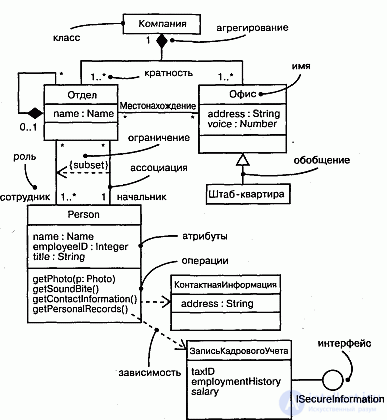
An association relationship corresponds to having a certain relationship between classes. This relationship is indicated by a solid line with additional special characters that characterize the individual properties of a particular association. As additional special characters, the name of the association can be used, as well as the names and multiplicity of the role-classes of the association. The name of the association is an optional element of its designation. If it is set, it is written with a capital (capital) letter next to the line of the corresponding association.
The simplest case of this relationship is the binary association. It connects exactly two classes and, as an exception, can associate a class with itself. For a binary association, a diagram can indicate the order of classes using a triangle in the shape of an arrow next to the name of this association. The direction of this arrow indicates the order of the classes, one of which is first (from the side of the triangle) and the other second (from the side of the vertex of the triangle). The absence of this arrow next to the name of the association means that the order of the classes in this relationship is not defined.
Higher-order associations are generally called the N-ary association. Such an association binds some relation of 3 or more classes, and one class can participate in the association more than once. The association class has a specific role in the appropriate relationship that can be explicitly indicated on the chart. Each instance of the N-ary association is an N-ary tuple of the values of objects from the corresponding classes.
An N-ary association is graphically denoted by a diamond , from which lines lead to the symbols of the classes of a given association. In this case, the rhombus is connected to the symbols of the corresponding classes with solid lines. Usually lines are drawn from the tops of the rhombus or from the middle of its sides. The name of the N-ary association is written next to the rhombus of the corresponding association.
The order of classes in the N-ary association, unlike the order of sets in the relation, is not fixed on the diagram. Some class can be attached to a diamond with a dotted line. This means that this class provides support for the properties of the corresponding N-ary association, and the N-ary association itself has attributes, operations, and / or associations. In other words, such an association, in turn, is a class with a corresponding designation in the form of a rectangle and is an independent element of the UML language — the Association Class.
Как уже указывалось, отдельный класс ассоциации имеет собственную роль в отношении. Эта роль может быть изображена графически на диаграмме классов. С этой целью в языке UML вводится в рассмотрение специальный элемент - конец ассоциации (Association End), который графически соответствует точке соединения линии ассоциации с отдельным классом. Конец ассоциации является частью ассоциации, но не класса. Каждая ассоциация имеет два или больше концов ассоциации. Наиболее важные свойства ассоциации указываются на диаграмме рядом с этими элементами ассоциации и должны перемешаться вместе с ними.
One of such additional designations is the name of the role of a separate class included in the association. The name of the role is a string of text near the end of the association for the corresponding class. It indicates the specific role played by the class, which is the end of the association in question. The role name is not a required element of designation and may be absent in the diagram.
Следующий элемент обозначений - кратность отдельных классов, являющихся концами ассоциации. Кратность отдельного класса обозначается в виде интервала целых чисел, аналогично кратности атрибутов и операций классов. Интервал записывается рядом с концом ассоциации и для N-арной ассоциации означает потенциальное число отдельных экземпляров или значений кортежей этой ассоциации, которые могут иметь место, когда остальные N-1 экземпляров или значений классов фиксированы.
Что касается других свойств отношения, ассоциации, то в случае их наличия, они могут рассматриваться в качестве атрибутов класса ассоциации и могут быть указаны на диаграмме обычным для класса способом в соответствующей секции прямоугольника класса.
Специальной формой или частным случаем отношения ассоциации является отношение агрегации , которое, в свою очередь, тоже имеет специальную форму - отношение композиции.
Отношение агрегации имеет место между несколькими классами в том случае, если один из классов представляет собой некоторую сущность, включающую в себя в качестве составных частей другие сущности.
Данное отношение имеет фундаментальное значение для описания структуры сложных систем, поскольку применяется для представления системных взаимосвязей типа «часть-целое». Раскрывая внутреннюю структуру системы, отношение агрегации показывает, из каких компонентов состоит система и как они связаны между собой. С точки зрения модели отдельные части системы могут выступать как в виде элементов, так и в виде подсистем, которые, в свою очередь, тоже могут образовывать составные компоненты или подсистемы. Это отношение по своей сути описывает декомпозицию или разбиение сложной системы на более простые составные части, которые также могут быть подвергнуты декомпозиции, если в этом возникнет необходимость в последующем.
Очевидно, что рассматриваемое в таком аспекте деление системы на составные части представляет собой некоторую иерархию ее компонентов, однако данная иерархия принципиально отличается от иерархии, порождаемой отношением обобщения. Отличие заключается в том, что части системы никак не обязаны наследовать ее свойства и поведение, поскольку являются вполне самостоятельными сущностями. Более того, части целого обладают своими собственными атрибутами и операциями, которые существенно отличаются от атрибутов и операций целого.
Графически отношение агрегации изображается сплошной линией, один из концов которой представляет собой не закрашенный внутри ромб. Этот ромб указывает на тот из классов, который представляет собой «целое». Остальные классы являются его «частями».
Отношение композиции является частным случаем отношения агрегации. Это отношение служит для выделения специальной формы отношения «часть-целое», при которой составляющие части в некотором смысле находятся внутри целого. Специфика взаимосвязи между ними заключается в том, что части не могут выступать в отрыве от целого, то есть с уничтожением целого уничтожаются и все его составные части.
Отношение обобщения является обычным таксономическим отношением между более общим элементом (предком) и более частным или специальным элементом (потомком). Данное отношение может использоваться для представления взаимосвязей между пакетами, классами, вариантами использования и другими элементами языка UML.
Применительно к диаграмме классов данное отношение описывает иерархическое строение классов и наследование их свойств и поведения. При этом предполагается, что класс-потомок обладает всеми свойствами и поведением класса-предка, а также имеет свои собственные свойства и поведение, которые отсутствуют у класса-предка. На диаграммах отношение обобщения обозначается сплошной линией с треугольной стрелкой на одном из концов. Стрелка указывает на общий класс (класс-предок или суперкласс), а ее отсутствие - на специальный класс (класс-потомок или подкласс).
Рядом со стрелкой обобщения может размещаться строка текста, указывающая на некоторые дополнительные свойства этого отношения. Данный текст будет относиться ко всем линиям обобщения, которые идут к классам-потомкам. При этом текст следует рассматривать как ограничение и записывать в фигурных скобках. В качестве ограничений могут быть использованы следующие ключевые слова языка UML:
{complete} - означает, что в данном отношении обобщения специфицированы все классы-потомки, и других классов-потомков у данного класса-предка быть не может;
{disjoint} - означает, что классы-потомки не могут содержать объектов, одновременно являющихся экземплярами двух или более классов;
{incomplete}- означает случай, противоположный первому, то есть, что на диаграмме указаны не все классы-потомки. В дальнейшем возможно восполнить их перечень не изменяя уже построенную диаграмму;
{overlapping} - означает, что отдельные экземпляры классов-потомков могут принадлежать одновременно нескольким классам.
Интерфейсы являются элементами диаграммы вариантов использования. Однако, при построении диаграммы классов, отдельные интерфейсы могут уточняться и в этом случае для их изображения используется специальный графический символ - прямоугольник класса с ключевым словом или стереотипом «interface». При этом секция атрибутов у прямоугольника отсутствует, а указывается только секция операций.
Объект (object) является отдельным экземпляром класса, который создается на этапе выполнения программы. Он имеет свое собственное имя и конкретные значения атрибутов. В силу самых различных причин может возникнуть необходимость показать взаимосвязи не только между классами модели, но и между отдельными объектами, реализующими эти классы. В таком случае может быть разработана диаграмма объектов, которая, хотя и не является канонической в метамодели языка UML, но имеет самостоятельное назначение.
Для графического изображения объектов используется такой же символ прямоугольника, что и для классов. Отличия проявляются при указании имен объектов, которые обязательно подчеркиваются. При этом запись имени объекта представляет собой строку текста « имя объекта:имя класса», разделенную двоеточием. Имя объекта может отсутствовать. В этом случае предполагается, что объект является анонимным. Отсутствовать может и имя класса. Тогда указывается просто имя объекта. Атрибуты объектов имеют конкретные значения.
При изображении диаграммы объектов нужно помнить, что каждый объект представляет собой экземпляр соответствующего класса, а отношения между объектами описываются с помощью связей (links), которые являются экземплярами соответствующих отношений. При этом все связи изображаются сплошными линиями.
Шаблон (template) или параметризованный класс (parametrized class) предназначен для обозначения такого класса, который имеет один или более не фиксированных формальных параметров. Он определяет множество классов, которые могут быть получены назначением этим параметрам конкретных значений. Обычно параметрами шаблонов служат типы атрибутов классов, такие как целые числа, перечисление, массив строк и другие. В более сложном случае формальные параметры могут представлять операции класса.
Графически шаблон изображается прямоугольником, к верхнему правому углу которого присоединен маленький прямоугольник из пунктирных линий. Большой прямоугольник может быть разделен на секции, как принято в обозначениях класса. В верхнем прямоугольнике указывается список формальных параметров, с помощью которых могут быть созданы классы на основе данного шаблона. В верхней секции шаблона записывается его имя по правилам записи имен классов.
Шаблон не может быть непосредственно использован в качестве класса, поскольку содержит неопределенные параметры. Чаще всего в качестве шаблона выступает некоторый суперкласс, параметры которого уточняются в его классах-потомках. В этом случае между ними существует отношение зависимости с ключевым словом "bind", когда класс-клиент может использовать некоторый шаблон для своей последующей параметризации. В более частном случае между шаблоном и формируемым от него классом имеет место отношение обобщения с наследованием свойств шаблона.

Comments
To leave a comment
System modeling
Terms: System modeling