Lecture
When reviewing state and activity diagrams, it was noted that, although these diagrams are used to specify the dynamics of system behavior, time is not explicitly present in them. The temporal aspect of behavior can be essential in the simulation of synchronous processes that describe the interaction of objects. To simulate the interaction of objects in time in the UML language, sequence diagrams are used.
Objects
The sequence diagram depicts only those objects that are directly involved in the interaction. The key point for sequence diagrams is the dynamics of the interaction of objects in time.
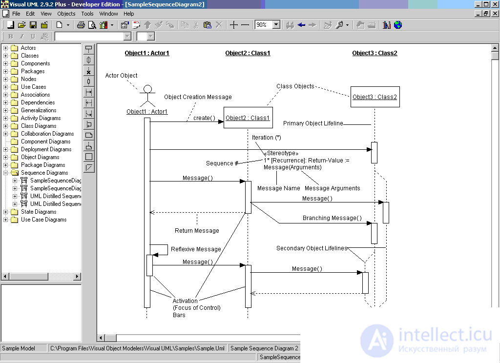
In UML, a sequence diagram has two dimensions. The first from left to right in the form of vertical lines, each of which depicts the life line of an individual object participating in the interaction. The extreme left of the diagram shows the object that initiated the interaction. To the right is another object that interacts directly with the first. Thus, all the objects in the sequence diagram form a certain order, determined by the order or degree of activity of the objects when interacting with each other.
Graphically, each object is depicted as a rectangle and is located at the top of its line of life. Inside the rectangle, the object name and class name are separated by a colon. In this case, the entire entry is emphasized, which is a sign of the object.
The second dimension of the sequence diagram is the vertical time axis, which is directed from top to bottom. The initial moment of time corresponds to the uppermost part of the diagram. Object interactions are implemented through messages that are sent from one object to another. Messages are displayed as horizontal arrows with the name of the message, and their order is determined by the time of occurrence. That is, the messages located in the sequence diagram above are initiated earlier than those below. The scale on the time axis is not indicated, since the sequence diagram only models the temporal ordering of early-later interactions.
The object lifeline is depicted as a dotted vertical line associated with a single object in the sequence diagram. The lifeline is used to indicate the period of time during which an object exists in the system and, therefore, can potentially participate in all its interactions. If an object exists in the system permanently, then its life line should continue along the entire plane of the sequence diagram from its highest to the lowest part.
Individual objects, having fulfilled their role in the system, can be destroyed to release the resources they occupy. For such objects, the line of life ends at the moment of its destruction. To indicate the moment of destruction of an object in the UML language, a special character in the form of the Latin letter “X” is used . Below this symbol, the dotted line is not depicted, since the corresponding object in the system no longer exists, and this object must be excluded from all subsequent interactions.
It is not necessary to create all the objects of the diagram at the initial moment of time. Individual objects can be created as needed, saving system resources and increasing its performance. In this case, the object's rectangle is depicted not in the upper part of the sequence diagram, but in the part that corresponds to the moment when the object was created. In this case, the object rectangle is vertically located in the place of the diagram that coincides along the time axis with the moment of its occurrence in the system. An object is necessarily created with its own life line and, possibly, with a focus of control.
During the operation of object-oriented systems, some objects can be in an active state, directly performing certain actions, or in a state of passive waiting for messages from other objects. In order to explicitly distinguish such activity of objects, a special concept is used in the UML language, called the focus of control. The focus of control is depicted in the form of an elongated narrow rectangle, the upper side of which indicates the beginning of receiving the focus of control of the object (the beginning of activity), and its lower side - the end of the focus of control (end of activity). A rectangle is located below the designation of the corresponding object and can replace its line of life if it is active throughout its length.
The periods of activity of an object can alternate with periods of its inactivity or expectation. In this case, such an object has several control foci. It is important to realize that only an existing object, which at this moment has a lifeline, can receive the control focus. If some object was destroyed, then it can no longer re-appear in the system. Instead, it can only be created by another instance of the same class, which, strictly speaking, will be another object.
In some cases, the initiator of interaction in the system may be an actor or an external user. In this case, the actor is depicted in the sequence diagram as the very first object on the left with its control focus. Most often, the actor and his control focus will exist in the system permanently, noting the characteristic user activity in initiating interactions with the system. In this case, the actor may have his own name or remain anonymous.
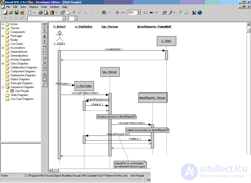
Sometimes an object can initiate recursive interaction with itself. The presence in many programming languages of special tools for constructing recursive procedures requires visualization of the corresponding concepts in the form of graphic primitives. In the sequence diagram, recursion is indicated by a small rectangle attached to the right side of the control focus of the object for which this recursive interaction is depicted.
In UML, each interaction is described by a set of messages that the objects participating in it exchange among themselves. A message (message) is a complete piece of information that is sent from one object to another. Receiving a message initiates the execution of certain actions aimed at solving a particular task by the object to which this message has been sent.
Thus, the messages not only transmit some information, but also require or imply the execution of the expected actions from the receiving object. Messages can initiate the execution of operations by the object of the corresponding class, and the parameters of these operations are transmitted along with the message. In the sequence diagram, all messages are ordered by the time of their occurrence in the simulated system. In such a context, each message has a direction from the object that initiates and sends the message to the object that receives it. Sometimes the sender of the message is called the client, and the recipient the server. Then the message from the client has the form of requesting some service, and the server’s response to the request after receiving the message can be associated with performing certain actions or sending the necessary information to the client, also in the form of a message.
Messages are depicted by horizontal arrows connecting the life lines or the foci of controlling two objects in a sequence diagram. In the UML language, there are several types of messages, each of which has its own graphic image:
- The first type of message is the most common and is used to call procedures, perform operations, or designate individual nested control threads. The beginning of this arrow always comes into contact with the focus of management or the life line of the client object that initiates this message. The end of the arrow is in contact with the life line of the object that receives this message and performs certain actions in response. The receiving object, as a rule, receives the control focus, becoming active;
- The second kind of message is used to indicate a simple control flow. Each such arrow indicates the execution of one step flow. Such messages are usually asynchronous, that is, they can occur at arbitrary points in time. The transfer of such a message, as a rule, is accompanied by receiving the focus of control of the object that received it;
- the third variant explicitly denotes an asynchronous message between two objects in a certain procedural sequence. An example of such a message is the interruption of an operation when an exception occurs. In this case, information on such a situation is transmitted to the caller to continue the process of further interaction;
- The fourth kind of message is used to return from the procedure call. An example would be a simple message about the completion of some calculations without providing the result of the calculations to the client object. In procedural control flows, this arrow may be omitted, since its presence is implicitly assumed at the end of the activation of the object. It is believed that each procedure call has its own pair - call return. For non-procedural control flows, including parallel and asynchronous messages, the return arrow must be explicitly indicated.
It is assumed that the time of message transmission is rather short compared with the processes of actions performed by objects, that is, no changes can occur during the time of message transmission with the corresponding objects. If this assumption cannot be considered fair, then the message arrow is depicted under a certain slope, so that the end of the arrow is located below its beginning.
In some cases, the object can send messages to itself, initiating the so-called reflective messages. Such messages are represented by a rectangle with an arrow, the beginning and end of which coincide. Similar situations arise, for example, when processing keystrokes on a keyboard when typing text into an edited document, when dialing digits of a subscriber's phone number.
Thus, in the UML language, each message is associated with a certain action that must be performed by the object that received it. An action can have some arguments or parameters, depending on the specific values of which a different result can be obtained. The message that causes this action will also have the appropriate parameters. Moreover, the parameter values of individual messages may contain conditional expressions, forming a branch or alternative paths of the main control flow.
For the image of the branching of the flow of control, two or more arrows are drawn, emerging from the same point of focus of the control object. In this case, the relevant conditions must be clearly indicated next to each of the arrows in the form of a guard condition. Watchdog conditions should mutually exclude the simultaneous transmission of alternative messages.
UML provides some standard actions to be taken in response to receiving the corresponding message. These actions can be explicitly indicated on the sequence diagram in the form of a stereotype next to the message to which they relate. In this case, they are written in quotes. The following message stereotypes are used:
- “Call” (call) - a message that requires calling the operation or procedure of the receiving object. If the message with this stereotype is reflexive, then it initiates a local operation call on the object that sent the message itself;
- “Return” is a message that returns the value of the completed operation or procedure to the object that called it. The result value may initiate a branching control flow;
- “Create” (create) - a message that requires the creation of another object to perform certain actions. The created object may receive control focus, or may not receive it;
- “Destroy” is a message with an explicit request to destroy the corresponding object. It is sent when it is necessary to stop unwanted actions from an object existing in the system, or when an object is no longer needed and must release the system resources it engages;
- “Send” (send) - indicates the sending of a signal to another object, which is asynchronously initiated by one object and received by another. The difference between the signal and the message is that the signal must be explicitly described in the class whose object initiates its transmission.
In addition to stereotypes, messages can have their own designation of the operation, the call of which they initiate at the receiving object. In this case, the name of the operation is written next to the arrow with parentheses in which the parameters or arguments of the corresponding operation can be specified. If there are no parameters, then parentheses should still be present after the operation name. Examples of such operations can be the following: “give the customer a cash amount (n)”, “establish a connection between subscribers (a, b)”, “make the input text invisible ()”, “give an audible alarm ()”.
In some cases, the implementation of certain actions on the sequence diagram may require an explicit specification of the time constraints imposed on the interval of operations or the transfer of messages. UML uses curly braces to record time constraints. Temporal constraints can refer both to the execution of certain actions by objects, and to the messages themselves, explicitly specifying the conditions for their transmission or reception. Unlike branching conditions, which must be met alternatively, temporal constraints are mandatory or prescriptive for their associated objects.
Time constraints may be recorded near the beginning of the arrow of the corresponding message. But most often they are written to the left of the arrow at the same level with it. If the time characteristic relates to a specific object, then the name of this object is recorded before the name of the characteristic and is separated from it by a period.
Examples of such restrictions on a sequence diagram can be situations where you need to explicitly specify the time during which a message is allowed to be sent from the client to the server or the client’s request to be processed by the server:
- {message_time_time_time_of_e_message <1 sec.};
- {time_expect_analyst <5 sec.};
- {time_of_package <10 seconds.};
- {object_1. alarm_signment_time> 30 sec.}.
Comments or notes may be included in sequence diagrams, associated with individual objects or messages. It uses the standard notation for a comment in the form of a rectangle with a curved upper right corner. Inside the rectangle is written the text of the comment in natural language.

Comments
To leave a comment
System modeling
Terms: System modeling