Lecture
When modeling the behavior of the system being designed or analyzed, it becomes necessary not only to present the process of changing its states, but also to detail the features of the algorithmic and logical implementation of the operations performed by the system.
To simulate the process of performing operations in the UML language, activity diagrams are used. The graphical notation used in them is in many respects similar to the state diagram notation, since these diagrams also contain state and transition designations. Each state in the activity diagram corresponds to the execution of some elementary operation, and the transition to the next state is performed only when this operation is completed.
Thus, activity diagrams can be considered a special case of state diagrams. They make it possible to implement in the UML language features of procedural and synchronous control, due to the completion of internal activities and actions. The main direction of using activity diagrams is the visualization of the features of the implementation of class operations when it is necessary to present algorithms for their implementation.
In the context of the UML language, an activity (activity) is a collection of separate calculations performed by an automaton, leading to some result or action (action). The activity diagram displays the logic and sequence of transitions from one activity to another, and the analyst’s attention focuses on the results. The result of the activity may lead to a change in the state of the system or the return of some value.
Action state
The action state is a special case of a state with some input action and at least one transition out of state. This transition implicitly assumes that the input action has already completed. The state of the action cannot have internal transitions, since it is elementary. The usual use of an action state is to simulate a single step of executing an algorithm (procedure) or control flow.
Graphically, the state of the action is depicted as a rectangle with rounded corners (Fig. 5). Inside this image, an action expression (action-expression) is written, which must be unique within a single activity diagram.
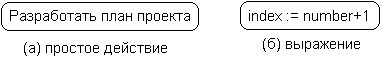
Fig. 5. Picture of action state
An action can be written in a natural language, some pseudocode, or a programming language. There are no additional or implicit restrictions on recording actions. It is recommended to use the verb with explanatory words as the name of a simple action. If the action can be represented in a certain formal form, then it is advisable to write it in the programming language in which it is supposed to implement a specific project.
Sometimes it becomes necessary to present some complex action in the activity diagram, which, in turn, consists of several simpler actions. In this case, you can use a special designation of the state of the sub-activity (subactivity state). Such a state is a graph of activity and is indicated by a special icon in the lower right corner of the symbol of the state of the action (Fig. 6). This construct can be applied to any element of the UML language that supports nesting of its structure. In this case, the icon can be additionally marked with the type of nested structure.
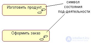
Fig. 6. Image of sub-activity status
Each activity diagram must have a single initial and only final state. They have the same designations as in the state diagram. In addition, each activity begins in the initial state and ends in the final state. The activity diagram itself is usually arranged in such a way that the actions follow from top to bottom. In this case, the initial state will be displayed at the top of the diagram, and the final one at the bottom.
Transition as an element of the UML language was considered in the state diagrams. When constructing an activity diagram, only non-triggers are used, that is, those that are performed immediately after the completion of the activity or the execution of the corresponding action. This transition takes the activity to the next state as soon as the action in the previous state ends. In the diagram, such a transition is represented by a solid line with an arrow .
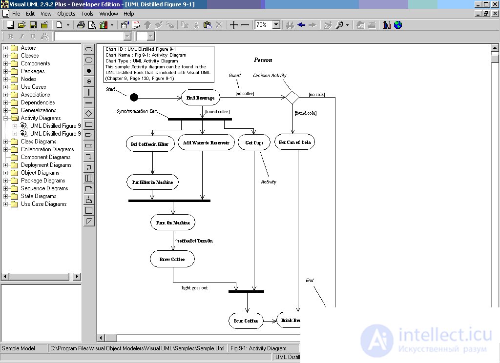
If a single transition comes out of the action state, it may not be marked in any way. If there are several such transitions, then only one of them can be executed. In this case, for each of these transitions, the guard condition must be explicitly written in brackets. The truth condition must be satisfied only one of them. A similar case occurs when a sequential activity is to be divided into alternative branches, depending on the value of some intermediate result. This situation is called a branch, and a special symbol is used to designate it.
Graphically, the branch in the activity diagram is indicated by a small rhombus, inside which there is no text. This diamond can include only one arrow from the state of the action, after which the flow of control must be continued along one of the mutually exclusive branches. It is accepted the incoming arrow to attach to the top or left vertex of the branch symbol. There may be two or more outgoing arrows, but each of them clearly indicates the corresponding guard condition in the form of a Boolean expression.
One of the drawbacks of conventional flowcharts is the problem of the image of parallel branches of individual computations. Since parallelization of computations significantly increases the overall speed of software systems, graphic primitives are needed to represent parallel processes. UML uses a special character for this purpose to separate and merge parallel computing or control flows. Such a symbol is a straight dash. As a rule, such a dash is depicted as a segment of a horizontal line, the thickness of which is somewhat wider than the main solid lines of the activity diagram. In this case, the division (concurrent fork) has one incoming transition and several outgoing ones, and a merge (concurrent join) has several incoming transitions and one outgoing transition.
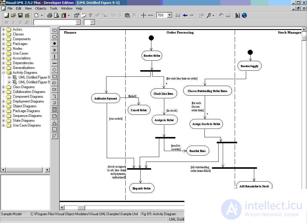
Activity diagrams can be used not only to specify calculation algorithms or control flows in software systems. No less important area of their application is related to business process modeling. Indeed, the activity of any organization is also a collection of individual actions aimed at achieving the desired result. However, in relation to business processes, it is desirable to associate each action with a specific division of the company. In this case, the division is responsible for the implementation of individual actions, and the business process itself is represented as a transition of actions from one division to another.
To simulate these features in the language UML uses a special design, called tracks (swimlanes). This refers to a visual analogy with the swimming lanes in the pool, if you look at the corresponding diagram. All action states in the activity diagram are divided into separate groups, which are separated from each other by vertical lines. Two adjacent lines form a track, and the group of states between these lines is performed by a separate division (department, group, department, branch) of the organization.
The names of the units are clearly indicated at the top of the track. Only transitions can intersect the track line, which, in this case, denotes the output or input of the control flow to the appropriate unit. The order of the tracks does not carry any semantic information and is determined by considerations of convenience.
In general, actions on the activity diagram are performed on one or another objects . These objects either initiate the execution of actions, or define some of their results. Actions specify calls that are passed from one activity graph object to another. Since from this perspective, objects play a certain role in understanding the process of an activity, it sometimes becomes necessary to indicate them explicitly in a diagram.
For a graphical representation of objects a class rectangle is used, with the difference that the name of the object is underlined. Further, after the name, an indication of the state of the object in brackets can be indicated. Such rectangles of objects are attached to the action states by the dependence of the dependence of the dotted line with the arrow. The corresponding dependency determines the state of a particular object after the execution of the previous action.
On the activity diagram with tracks, the location of the object may have some additional meaning. Namely, if the object is located on the border of two tracks, then this may mean that the transition to the next action state in the adjacent track is associated with the readiness of some document (the object is in some state). If the object is located entirely inside the track, then the state of this object is entirely determined by the actions of this track.
For the synchronization of individual actions in the activity diagram, no additional designations are used, since synchronization of parallel processes can be implemented using split-merge transitions.

Comments
To leave a comment
System modeling
Terms: System modeling