Lecture
The complete design of a software system is a set of models of the logical and physical layers, which must be consistent with each other. In UML, for the physical representation of system models, implementation diagrams (implementation diagrams) are used, which include a component diagram and a deployment diagram .
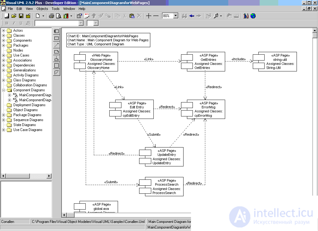
The component diagram, unlike the previously considered diagrams, describes the features of the physical representation of the system. It allows you to define the architecture of the system being developed by establishing dependencies between software components, in the role of which the source and executable code can act. The main graphic elements of the component diagram are components, interfaces and dependencies between them.
The component diagram is developed for the following purposes:
- visualization of the overall structure of the source code of the software system;
- specifications of the executable version of the software system;
- ensuring repeated use of individual pieces of software code;
- representations of conceptual and physical database schemas.
In the development of component diagrams are involved as system analysts and architects, and programmers. The component diagram provides a consistent transition from a logical view to a specific project implementation in the form of program code. Some components can exist only at the stage of compilation of the program code, others at the stage of its execution. The component diagram reflects the general dependencies between components, considering the latter as classifiers.
Components
To represent physical entities in the UML language, a special term is used - the component . The component implements a certain set of interfaces and serves for a general designation of the elements of the physical representation of the model. For the graphic representation of the component, a special symbol is used - a rectangle with two smaller rectangles inserted on the left. Inside the large rectangle is written the name of the component and, if necessary, some additional information. The image of this symbol may vary slightly depending on the nature of the information associated with the component.
The name of a component follows the general rules for naming model elements in UML and can consist of any number of letters, numbers, and some punctuation marks.
A single component can be represented at the type level or at the instance level. The graphic image is the same in both cases, but the rules for writing the name of the component are different. If a component is presented at the type level, then only the type name with a capital letter is written as its name. If a component is represented at the instance level, then ':' is recorded as its name. In this case, the entire line of the name is underlined.
The names of executable files (with the extension exe after the separator point), dynamic libraries (dll extension), Web pages (html extension), text files (txt or doc extensions) or help files (hip), database files (DB) or source files (h, cpp for C ++, java for Java), scripts (pi, asp) and others.
Since the concrete implementation of the logical representation of the system model depends on the software tools used, the names of the components are determined by the syntax features of the corresponding programming language.
In some cases, information about the name of the enclosing package and the specific version of the implementation of this component can be added to the simple name of the component. In this case, the version number is written as the marked value in curly braces. In other cases, the component symbol can be divided into sections to explicitly indicate the names of the interfaces implemented in it.
Since the component as an element of the physical implementation of the model represents a separate code module, it is sometimes commented on with indication of additional graphic symbols illustrating the specific features of its implementation. These additional notations for notes are not specified in UML, but their use simplifies the understanding of the component diagram, increasing the visibility of the physical representation.
In the UML language, there are three types of components :
- deployments that provide the direct execution of the system of its functions. Such components can be dynamic link libraries with dll extension, hypertext markup language web pages with html extension and help files with hlp extension;
- working products. As a rule, these are files with source texts of programs, for example, with extensions h or cp for C ++;
- executions, which are executable modules - files with the exe extension.
These elements are sometimes called artifacts, while emphasizing their complete informational content, depending on the specific technology for implementing the respective components.
Another way of specifying different kinds of components is to explicitly indicate its stereotype of the component before the name. The following stereotypes are defined for components in UML:
- library (library) - defines the first kind of component, which is represented in the form of a dynamic or static library;
- table (table) - also defines the first kind of component, which is represented in the form of a database table;
- file (file) - defines the second type of component, which is represented in the form of files with source codes of programs;
- document - defines the second kind of component,. which is presented in the form of a document;
- executable — defines the third kind of component that can be executed in a node.
The next element of the component diagram are interfaces . In general, the interface is graphically represented by a circle that connects to the component with a line segment without arrows. The interface name must begin with a capital " I " and be written next to the circle. Semantically, a line means the implementation of an interface, and the presence of interfaces at a component means that this component implements a corresponding set of interfaces.
Another way of representing the interface in the component diagram is its image in the form of a class rectangle with an “interface” stereotype and possible sections of attributes and operations. Typically, this designation is used to represent the internal structure of the interface, which may be important for implementation.
When developing software systems, the interfaces provide not only compatibility of various versions, but also the ability to make significant changes to some parts of the program without changing other parts of it. Thus, the assignment of interfaces is much broader than the specification of interaction with system users (actors).
In the general case, the dependency relationship was also considered earlier. Recall that dependence is not an association, but serves to represent only the fact of the existence of such a connection, when a change in one element of the model influences or leads to a change in another element of the model. The dependency relationship in the component diagram is represented by a dotted line with an arrow directed from the client (dependent element) to the source (independent element).
Dependencies may reflect the links of the program modules at the compilation and generation of the object code. In another case, the dependency may reflect the presence in the independent component of the descriptions of classes that are used in the dependent component to create the corresponding objects. With reference to the component diagram, dependencies can bind components and the interfaces imported by this component, as well as various types of components to each other.
In the first case, draw an arrow from the client component to the imported interface. The presence of an arrow means that the component does not implement the corresponding interface, but uses it in the course of its execution. Moreover, on the same diagram there may be another component that implements this interface.
Another instance of a dependency relationship in a component diagram is the relationship between different kinds of components. The presence of such a dependency means that making changes to the source code of programs or dynamic libraries leads to changes in the component itself. The nature of the changes may be noted additionally.
The component diagram can also show the dependencies between the components and the classes implemented in them. This information is important to ensure that the logical and physical representations of the system model are consistent. If it is necessary to emphasize that a certain component implements separate classes, then an extended rectangle symbol is used to designate a component. In this case, the component rectangle is divided into two sections by a horizontal line. The upper section is used to record the name of the component, and the lower section - to indicate additional information.
Inside the component symbol, other elements of the graphic notation can be represented, such as classes (component of type-level) or objects (component of instance level). In this case, the component symbol is depicted in such a way as to accommodate these additional characters.
Objects that are in a separate component instance are represented as nested in the symbol of this component. Such nesting means that the execution of a component entails the execution of the corresponding objects.
The development of the component diagram assumes the use of information both about the logical representation of the system model and about the features of its physical implementation. Prior to development, it is necessary to make decisions about the choice of computing platforms and operating systems on which the system is supposed to be implemented, as well as the choice of specific databases and programming languages.
After that, you can proceed to the general structuring of the component diagram. First of all, it is necessary to decide which physical parts (files) the software system will consist of. At this stage, attention should be paid to such an implementation of the system that would provide not only the possibility of code reuse due to the rational decomposition of components, but also the creation of objects only when necessary.
The point is that the overall performance of a software system essentially depends on the rational use of computing resources. For this purpose, most of the class descriptions, their operations and methods should be transferred to dynamic libraries, leaving only the most necessary program code fragments for program initialization in the executable components.
After the general structuring of the physical representation of the system, it is necessary to supplement the model with interfaces and database schemas. When developing interfaces, one should pay attention to the coordination (docking) of various parts of the software system. Inclusion in the database schema model involves the specification of individual tables and the establishment of information links between the tables.
The final stage of the construction of the component diagram is associated with the establishment and application to the diagram of the mutual relations between the components, as well as the relations of realization. These relationships should illustrate all the most important aspects of the physical implementation of the system, starting with the features of compiling the source code of programs and ending with the execution of individual parts of the program at the stage of its implementation. For this purpose, you can use different types of graphic images of components.
When developing a component diagram, one should adhere to the general principles of creating models in the UML language. In particular, it is necessary to use the components and stereotypes already existing in the UML language. For most typical projects, this set of elements may be sufficient to represent the components and the dependencies between them.
If the project contains some physical elements that are not described in the UML language, then you should use the extension mechanism and use additional stereotypes for individual atypical components or labeled values to clarify their individual characteristics.
It should be noted that the component diagram, as a rule, is developed together with the deployment diagram, on which information is presented on the physical location of the components of the software system at its individual nodes.

Comments
To leave a comment
System modeling
Terms: System modeling