Lecture
In a number of cases, an object that we model or control by us can qualitatively change in the course of its operation. Before that, we considered cases when quantitatively the individual parameters of the system were changed, the values of its individual variables, but the equations themselves, the names or the number of variables, their relationships did not change. In structurally changing systems, for example, old connections may disappear or new connections may appear, elements of the system. That is, in the process of modeling, the structure of the simulated system itself may change. Accordingly, the model should also be able to change its properties and equations during the modeling process.
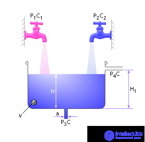
Task 1. Two different liquids are poured into the tank. There is a drain hole in the bottom of the tank and an emergency drain hole on the side (see fig. 13.1). The purpose of imitation is the analysis of system behavior. To do this, we discuss the equations that model the dynamics of the system behavior.
| |
| Fig. 13.1. Simulated system |
We denote: P - fluid consumption [l / h], C - concentration [kg / m 3 ], S - area [m 2 ], V - volume of liquid [m 3 ]. Denote the concentration of input streams as C 1 and C 2 . Both flows are mixed in the tank, resulting in a liquid with some average concentration C. Naturally, the liquid will be drained through the outlets with the concentration C. Then: d C / d t = ( P 1 · C 1 + P 2 · C 2 - P 3 · C - P 4 · C ) / V.
The change in concentration depends on the ratio of the flow rate of the fluid (incoming and outgoing from the tank) and the concentration of the respective streams: d V / d t = P 1 + P 2 - P 3 - P 4 .
The change in the volume of fluid in the tank depends on the ratio of the flow rate of the fluid (supplied and removed from the tank) of the respective flows: H = V / S.
The height of the liquid in the tank depends on the volume and area of the tank: P 3 = a · H.
The flow of fluid through the drain hole in the bottom of the tank depends on the liquid column - the larger the liquid column, the more it presses on its lower layers and the faster the liquid flows out of the tank (here a is the coefficient of proportionality).
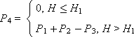
To take into account the impact on the operation of the emergency valve system, we note that if the height H of the fluid in the tank exceeds the level of H 1 , the liquid will begin to overflow through the emergency drain hole on the side, otherwise there is no flow through the hole. Mathematically, this fact can be expressed by the following system:
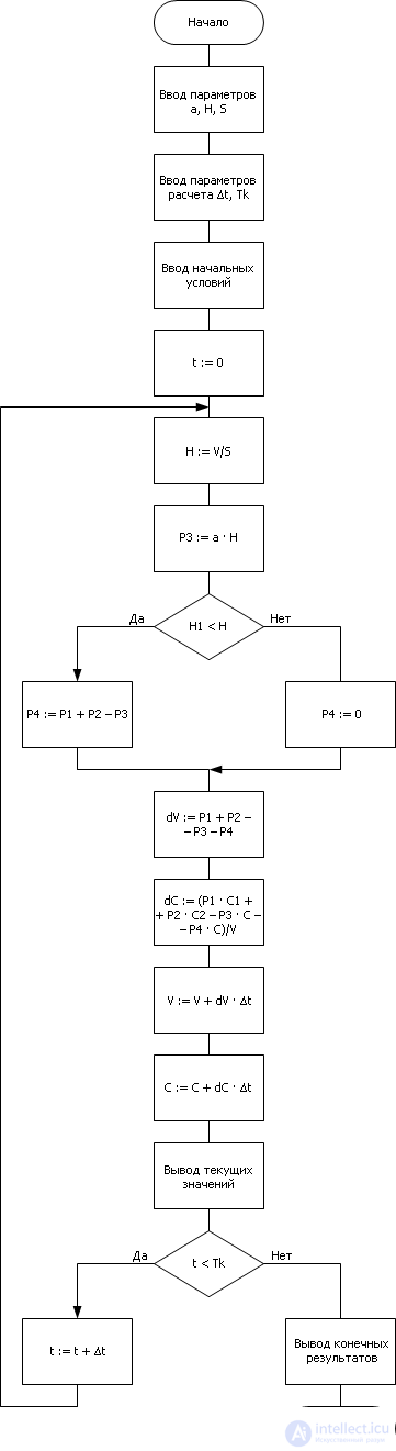
The algorithm for implementing such a model is shown in the flowchart (see Figure 13.2). Please note: in comparison with previous implementations, the IF condition block has appeared - it is used to connect one or another variant of the equation. The structure change is simulated by a conditional block .
| |
| Fig. 13.2. Block diagram of an algorithmic implementation structurally tunable model |
If you implement a model in a formal language, the entry will look like the one shown below. Recall that this notation uses the language of equations.
|

Comments
To leave a comment
System modeling
Terms: System modeling