Lecture
The physical representation of a software system cannot be complete if there is no information on which platform and on which computing facilities it is implemented. If a program is being developed that runs locally on the user's computer and does not use peripheral devices and resources, then there is no need to develop additional diagrams. When developing corporate applications, the presence of such diagrams can be extremely useful for solving problems of rational distribution of components in order to efficiently use distributed computing and communication resources of the network, ensure security, and others.
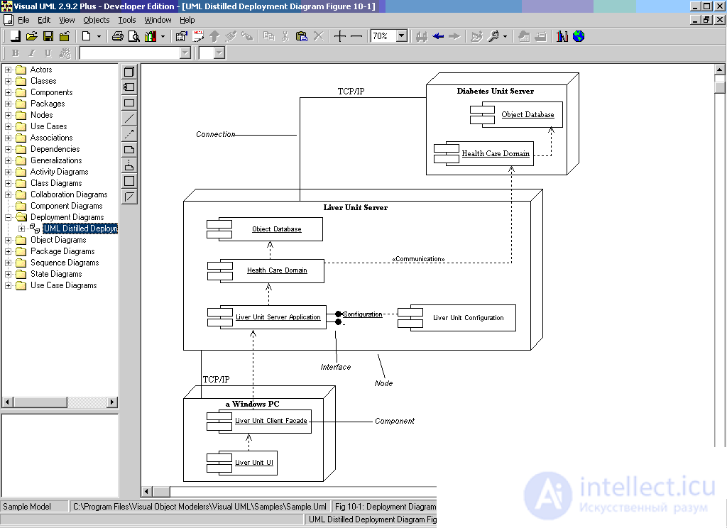
Deployment diagrams are intended to represent the overall configuration and topology of a distributed software system in UML.
The deployment diagram is intended for visualization of program elements and components that exist only at the stage of its execution (runtime). In this case, only the components of the program are represented, which are executable files or dynamic libraries. Those components that are not used at runtime are not shown in the deployment diagram. So, components with source code of programs can be present only on the component diagram. They are not shown on the deployment diagram.
The deployment diagram contains graphic representations of the processors, devices, processes, and the connections between them. Unlike the logical presentation diagrams, the deployment diagram is uniform for the system as a whole, since it must fully reflect the features of its implementation. Development of a deployment chart is usually the last step in the specification of a software system model.
When developing a deployment chart, the following objectives are pursued:
- determine the distribution of system components across its physical nodes;
- show the physical connections between all nodes of the system implementation at the stage of its execution;
- identify system bottlenecks and reconfigure its topology to achieve the required performance.
Deployment diagrams are developed jointly by system analysts, network engineers and system engineers.
Knot
A node (node) is a certain physically existing element of the system that has a certain computational resource. The presence of a certain amount of electronic or magneto-optical memory or a processor can be considered as a computing resource of a node. In the latest version of UML, the concept of a node is expanded and may include not only computing devices, but also other mechanical or electronic devices, such as sensors, printers, modems, digital cameras, scanners and manipulators.
Graphically, a node is depicted in the deployment diagram as a three-dimensional cube . The node has its own name, which is indicated inside its graphic symbol. The nodes themselves can be represented both as types and as instances.
In the first case, the node name is written without underscore and begins with a capital letter. In the second, the instance node name is written as . The name of the node type indicates some kind of nodes present in the system model.
For example, the hardware of the system may consist of several computers, each of which corresponds to a separate instance node in the model. However, all these instance nodes belong to the same type of node, namely, the node with the name of the Computer type.
As with the component diagram, node images can be extended to include some additional information about the node specification. If the additional information relates to the node name, then it is recorded under this name in the form of a tagged value.
If you need to explicitly specify the components that are located on a separate node, then this can be done in two ways. The first allows you to split the graphic symbol of a node into two sections by a horizontal line. In the upper section, write the name of the node, and in the lower section the components placed on this node. The second method allows to show nodes with embedded images of components in the deployment diagram. However, it should be borne in mind that only executable components can act as such nested components.
In addition to the node name, various stereotypes can be used that explicitly specify the purpose of this node. Although stereotypes for nodes are not defined in UML, the following variants are found in the literature: “processor”, “sensor”, “modem”, “network” and others that can be independently determined by the developer. In the deployment diagrams for various physical devices, special graphical symbols are also used to explain and reveal the purpose or functions performed by the device.
In addition to the images of the nodes in the deployment diagram, the relationships between them are indicated. Relationships are the physical connections between nodes and the dependencies between nodes and components, the images of which can also be present in the deployment diagrams.
Connections are a type of association and are depicted as line segments without arrows. The presence of such a line indicates the need for a physical channel for the exchange of information between the corresponding nodes. The nature of the connection can be further specified by a note, marked with a value or a restriction.
In addition to connections, a dependency relationship between a node and components deployed on it may be present in the deployment diagram. This method is an alternative to the embedded image of the components inside the node symbol, which is not always convenient, since it makes the symbol too voluminous. Therefore, with a large number of components deployed on a node, the corresponding information can be represented in the form of a dependency relationship.
Deployment diagrams can have a complex structure, including embedded components, interfaces, and other hardware devices.
The development of a deployment chart begins with the identification of all hardware, mechanical, and other types of devices that are necessary for the system to perform all its functions. First of all, the computational nodes of the system with memory and / or processor are specified. In this case, the stereotypes used in the UML language are used, and if they are not available, the developers can define new stereotypes. Separate hardware requirements can be specified in the form of constraints, properties, and labeled values.
Further construction of the deployment diagram is associated with the placement of all executable components of the diagram on the nodes of the system. If the individual executable components were not placed, then this situation should be excluded by introducing additional nodes containing the processor and memory into the model.

Comments
To leave a comment
System modeling
Terms: System modeling