Lecture
Each state diagram in UML describes all possible states of one instance of a certain class and possible sequences of its transitions from one state to another, that is, it models all changes in the states of an object as its response to external influences.
State diagrams are most often used to describe the behavior of individual objects, but can also be used to specify the functionality of other components of models, such as use cases, actors, subsystems, operations, and methods.
A state diagram is a special type of graph that represents an automaton. The vertices of the graph are the possible states of the automaton represented by the corresponding graphic symbols, and the arcs denote its transitions from state to state. State diagrams can be nested into each other for a more detailed view of the individual elements of the model.
UML automata
In the UML metamodel, an automaton is a package in which a set of concepts is defined that are necessary to represent the behavior of the modeled entity in the form of a discrete space with a finite number of states and transitions.
The duration of a system in any of the possible states significantly exceeds the time it takes to transition from one state to another. It is assumed that in the limit the transition time may be zero (unless otherwise specified), that is, the change of object states can occur instantaneously.
The behavior of the automaton is modeled as a sequential movement along the graph from vertex to vertex, taking into account the orientation of the arcs connecting them.
For the machine, the following mandatory conditions must be met:
- the state in which the object can go, is determined only by its current state and does not depend on the prehistory;
- at each instant of time, the automaton can only be in one of its states. At the same time, the machine can be in a separate state for an arbitrarily long time, if no events occur;
- the time the machine is in a particular state, as well as the time to reach a particular state is not specified in any way;
- the number of states of the automaton must be finite and all of them must be explicitly specified. Separate pseudostates may not have specifications (initial and final states). In this case, their purpose and semantics are completely determined from the context of the model and the state diagram under consideration;
- graph of an automaton should not contain isolated states and transitions. For each state, except the initial one, the previous state must be defined, and each transition must connect two states of the automaton;
- an automaton should not contain conflicting transitions, when an object can simultaneously go into two or more subsequent states (except for the case of parallel subtotoms). In the UML language, the elimination of conflicts is possible on the basis of the introduction of guard conditions
The concept of state is fundamental not only in the UML metamodel, but also in applied system analysis. The whole concept of a dynamic system is based on the concept of state. The semantics of the state in the UML language has a number of specific features.
In the UML language, a state is an abstract metaclass used to model a particular situation during which certain conditions are fulfilled. A state can be specified as a set of specific values of the attributes of a class or object. A change in individual attribute values will reflect a change in the state of the class or object being modeled.
The state on the diagram is depicted as a rectangle with rounded vertices . The rectangle can be divided into two sections by a horizontal line. If only one section is specified, then only the state name is recorded in it. If there are two sections, the first of them contains the name of the state, and the second list of some internal actions or transitions in this state. An action in the UML language is a certain atomic operation, the execution of which leads to a state change or the return of some value (for example, “true” or “false”).
The name of the state is a string of text that reveals its meaningful meaning. The name is always written with a capital letter. Since the state of the system is an integral part of its functioning, it is recommended that verbs be used as a name in the present tense (ringing, typing, waiting) or relevant participles (busy, free, transmitted, received). The name of the state may be missing and in this case the state is anonymous. If there are several anonymous states in the diagram, then they should differ from each other.
The list of internal actions contains a list of actions or activities that are performed while the simulated element is in a given state. Each of the actions is recorded as a separate line and has the following format:
<action label="" '="" expression-action="">
The action label indicates the circumstances or conditions under which the activity defined by the action expression will be performed. In this case, the action expression can use any attributes and relationships that belong to the namespace or context of the object being modeled. If the list of action expressions is empty, then the slash in the form of a slash '/' may not be specified.
The list of action labels has fixed values that cannot be used as event names. These values are as follows:
- entry - this label indicates the action specified by the action expression following it, which is executed at the moment of entering this state (the input action);
- exit - this label indicates the action specified by the action following it, which is executed at the time of exit from this state (output action);
- do - this label specifies the activity to be executed (“do activity”) that runs for as long as the object is in this state, or until the calculation specified by the action expression following it ends. In this case, when the event ends, the corresponding result is formed;
- include - this label is used to refer to a sub-machine, while the following action expression contains the name of this sub-machine.
In all other cases, the action label identifies the event that triggers the corresponding action expression. These events are called internal transitions and are semantically equivalent to transitions to this state itself, except for the peculiarity that the exit from this state or re-entry into it does not occur and the input and output actions are not performed.
The initial state is a special case of a state that does not contain any internal actions (pseudo-state). In this state, the default object is at the initial moment of time. It serves to indicate on the diagram of the graphic area, from which the process of changing states begins. Graphically, the initial state in the UML language is denoted as a filled circle, from which only the arrow corresponding to the transition can go.
At the topmost level of the object representation, the transition from the initial state can be marked by the event of creation (initialization) of this object. Otherwise, the transition is not marked in any way. If this transition is not marked, then it is the first transition to the state following it.
The final state is a special case of the state, which also does not contain any internal actions (pseudostate). In this state, there will be a default object after the completion of the automaton operation at the final time instant. It serves to indicate on the diagram of the graphic area in which the process of changing states or the life cycle of a given object is completed. Graphically, the final state in the UML language is denoted as a filled circle, placed in a circle, which can only enter the arrow corresponding to the transition.
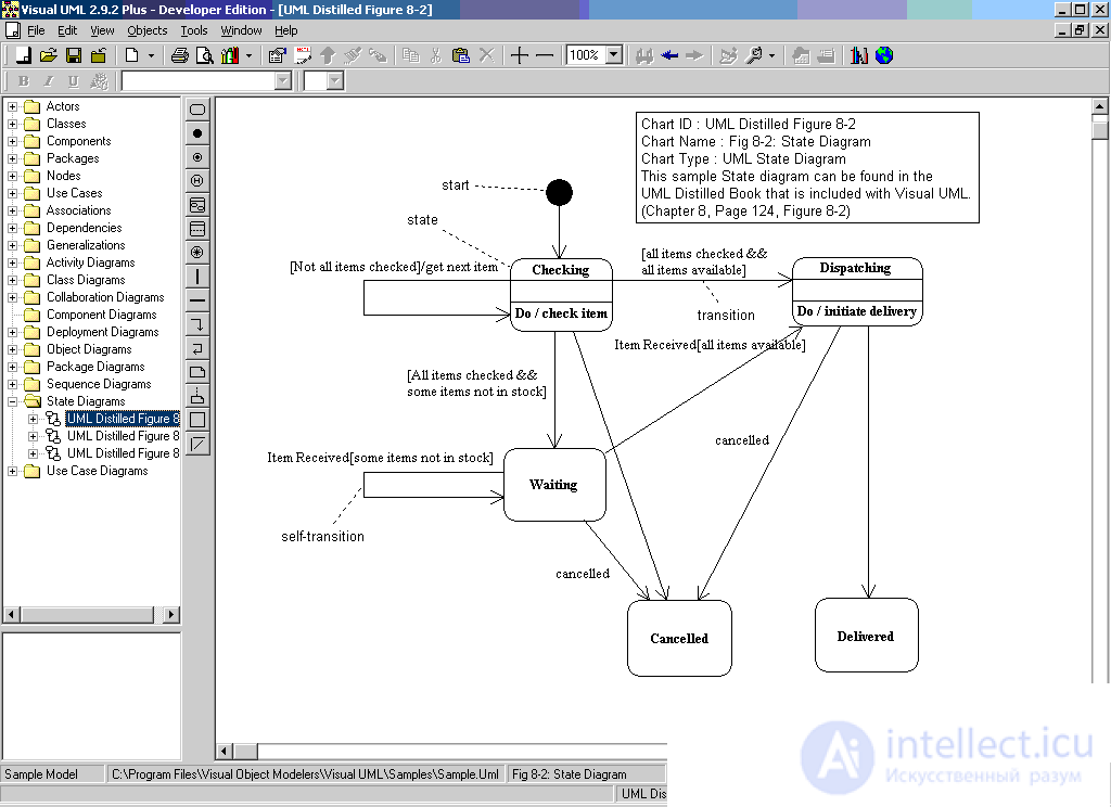
A simple transition is a relationship between two successive states, which indicates the fact that one state of an object changes to another. If a simulated object stays in the first state and is accompanied by certain actions, the transition to the second state will be possible only after these actions have been completed and, possibly, after some additional conditions, called watchdog conditions, have been fulfilled.
In the state diagram, the transition is represented by a solid line with an arrow that is directed to the target state. Each transition can be marked with a string of text that has the following general format:
'[' ']' .
In this case, the event signature describes some event with the necessary arguments:
'(' ')'.
Event (event) is an independent element of the language UML. Formally, an event is a specification of some fact that takes place in space and in time. About the events they say that they "occur", while individual events must be ordered in time. After the occurrence of a certain event, it is no longer possible to return to previous events, unless such a possibility is explicitly provided for in the model.
The semantics of the concept of an event fixes attention on the external manifestations of qualitative changes that occur during the transition of a simulated object from state to state. In the UML language, events play the role of stimuli that initiate transitions from one state to another. Signals, calls, the end of fixed periods of time or the moments of the end of certain actions can be considered as events.
The event name identifies each individual transition in the state diagram and may contain a line of text starting with a lowercase letter. In this case, the transition is considered to be a trigger, that is, one that specifies a trigger event. If no line of text is indicated next to the transition arrow, then the corresponding transition is non-triggering, and in this case the context of the state diagram should follow after what activity it has completed. Parentheses may follow the event name to explicitly set the parameters of the corresponding trigger event. If there are no such parameters, then the list of parameters with brackets may be missing.
The guard condition, if any, is always written in right brackets after the trigger event and is a Boolean expression. The semantics of this expression must explicitly follow from the context of the state diagram, and the syntax of the object constraint language can be used to write the expression.
The introduction of the watchdog condition allows you to explicitly specify the semantics of its triggering. However, the calculation of the truth of the watchdog condition occurs only after the occurrence of an associated trigger event that initiates the corresponding transition.
In the general case, there can be several transitions from the same state with the same trigger event. At the same time, no two watchdog conditions should simultaneously take the value “true”. Each of the watchdog conditions must be calculated each time a corresponding trigger event occurs.
An example of a trigger event is the disconnection of a telephone connection with an Internet service provider after the end of the email download by the client mail program (with remote access to the Internet). In this case, the watchdog condition is nothing more than an answer to the question: “Is the client's mailbox empty on the provider's server?”. In the case of a positive answer - “true”, you should disconnect the connection with the provider, which is done automatically by the mail client program. In the case of a negative answer - “false”, one should remain in the state of downloading mail and not terminate the telephone connection.
The action expression is executed only when the transition is triggered. It represents an atomic operation that is performed immediately after the triggering of the corresponding transition before the start of any action in the target state. The atomic nature of an action means that it cannot be interrupted by any other action until it is completed. This action can affect both the object itself and its environment, if it clearly follows from the context of the model.
In general, an action expression can contain a whole list of individual actions, separated by the symbol “ ; ". All list actions must be different and follow the order of recording. There are no restrictions on the syntax for writing action expressions. The main condition that the record was clear to the developers of the model and programmers. As a rule, action expressions are written in one of the programming languages that are supposed to be used to implement the model.
Compound state and substate
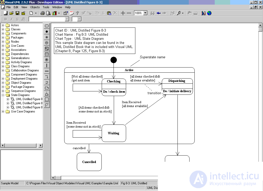
A composite state is a complex state consisting of other states nested within it. Nested states appear in relation to a complex state as substates. Although there is a composition relation between them, graphically all the vertices of the diagram that correspond to the nested states are depicted inside the composite state symbol. In this case, the dimensions of the graphic symbol of the composite state increase, so as to accommodate all the substates.
Fig. 1. Image of composite state
A composite state may contain two or more parallel sub-machines or several consecutive substates. Each composite state can be refined only by one of the indicated methods. At the same time, any of the substates can also be a composite state and contain other nested substates within it. The number of levels of nesting of composite states is not limited in the UML language.
Sequential substates are used to simulate the behavior of an object, during which at each moment of time an object can be in one and only one substate. The behavior of the object in this case is a sequential change of substates, starting from the initial and ending at the final. Introduction to the consideration of consecutive substates allows to take into account more subtle logical aspects of the internal behavior of the object.
A composite state can contain initial and final states as nested substates. In this case, the initial substate is the initial state when an object transitions to this composite state. If a composite state contains a final substate within itself, then a transition to this nested final state means the completion of the finding of the object in this nested state. For consecutive substates, the initial and final states must be unique in each composite state.
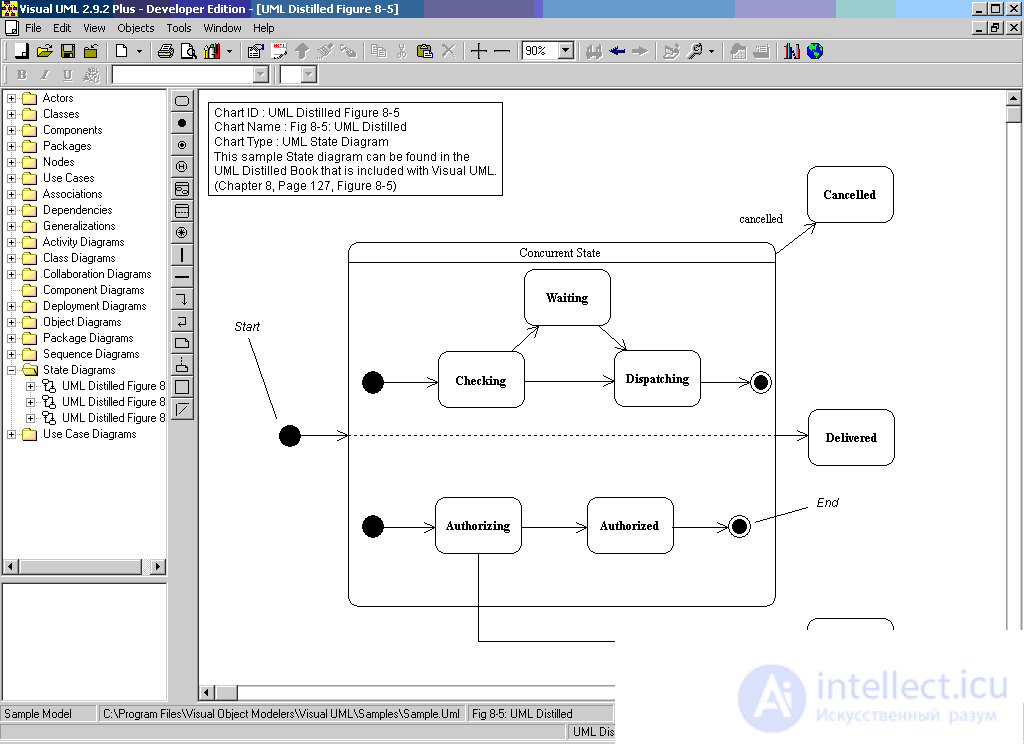
Concurrent substates (concurrent substates) allow you to specify two or more submachines that can be executed in parallel within a composite event. Each of the sub-machines occupies a certain region or region within a composite state, which is separated from the rest by a horizontal dashed line. If the state diagram has a composite state with nested parallel substates, then the object can simultaneously be in each of these substates.
Separate parallel substates can consist of several consecutive substates (sub-machines 1 and 3 in Fig. 2).
Fig. 2. Image of a composite state with nested parallel substates
Since each region of a nested state specifies a certain submachine, its own initial and final substates can be defined for each of the nested submachines (Fig. 2). When switching to this composite state, each of the sub-machines turns out to be in its initial substate. Then parallel execution of each of these sub-machines occurs, and the exit from the composite state will be possible only in the case when all the sub-machines will be in their final sub-states. If any of the sub-machines came to their final state earlier than the others, then it should wait until the other sub-machines come to their final states.
In some cases, it is desirable to hide the internal structure of a composite state. For example, a separate submachine that specifies a composite state may be so large in size that its visualization makes it difficult to get a general view of the state diagram. In such a situation, it is allowed not to disclose this composite state on the initial diagram, but to indicate in the lower right corner a special pictogram symbol (Fig. 3). In the following, the state diagram for the corresponding sub-machine can be shown separately with the necessary comments.
Fig. 3. Compound state with hidden internal structure
As noted above, the rules for constructing an ordinary automaton do not allow for the prehistory to be taken into account in the process of modeling the behavior of objects. However, the functioning of a number of systems is based on the possibility of exiting from individual states and then returning to the same state. In this case, it may be necessary to take into account that part of the activity that was performed at the time of exit from this state, so as not to start its implementation from the beginning. For this purpose, a historical state exists in the UML language .
The history state is used in the context of a composite state. It is used to memorize that of the successive substates that was current at the time of exit from the composite state. At the same time, there are two types of historical state: recent and old (Fig. 4).
Fig. 4. Image of the recent (a) and old (b) historical state
Недавнее историческое состояние (shallow history state) обозначается в форме небольшой окружности, в которую помещена латинская буква «Н» (рис. 4а). Это состояние обладает следующей семантикой. Во-первых, оно является первым подсостоянием в составном состоянии, и переход извне в это составное состояние должен вести непосредственно в это историческое состояние. Во-вторых, при первом попадании в недавнее историческое состояние оно не хранит никакой истории (история пуста), то есть заменяет собой начальное состояние подавтомата.
Далее следует последовательное изменение вложенных подсостояний. Если в некоторый момент происходит выход из вложенного состояния (например, в случае некоторого внешнего события), то это историческое состояние запоминает то из подсостояний, которое являлось текущим на момент выхода. При следующем входе в это же составное состояние историческое подсостояние уже имеет непустую историю и сразу отправляет подавтомат в запомненное подсостояние, минуя все предшествующие ему подсостояния.
Историческое состояние теряет свою историю в тот момент, когда подавтомат доходит до своего конечного состояния. При этом недавнее историческое состояние запоминает историю только того подавтомата, к которому он относится.
С другой стороны, запомненное состояние, в свою очередь, также может являться составным состоянием. Давнее историческое состояние (deep history state) обозначается в форме небольшой окружности, в которую помещена латинская буква «Н» с символом «*» (рис. 4б) и служит для запоминания всех подсостояний любого уровня вложенности для текущего подавтомата.
The concept of transition considered above is quite sufficient for most typical computational problems. However, modern software systems can implement a very complex logic of the behavior of their individual components. It may turn out that for an adequate representation of the process of changing states, the semantics of the ordinary transition is insufficient for them. For this purpose, additional notations and properties are specified in the UML language, which individual transitions in the state diagram may have.
In some cases, the transition may have several source states and several target states. Such a transition was called a parallel transition .
Graphically, such a transition is represented by a vertical dash. If a parallel transition has two or more incoming arcs, it is called a join. If it has two or more outgoing arcs, then it is called a fork. The text string of the parallel transition specification is written next to the dash and applies to all incoming or outgoing arcs.
Triggering parallel transition occurs as follows. The transition-connection is executed if a trigger event occurs for all initial states of this transition, and the guard condition, if any, is fulfilled. When a transition-connection is triggered, all the initial states of the transition simultaneously leave and the transition to the target state occurs. In this case, each of the initial states of the transition must belong to a separate submachine that is part of the automaton.
In the case of branching, the automaton is divided into two sub-machines that form parallel branches of nested substates. After the transition is triggered, the simulated object will simultaneously be in all the target states of this transition. Further, the process of changing states will proceed according to the rules for compound states.
A transition, the arrow of which is connected to the boundary of a certain composite state, denotes a transition to a composite state. Such a transition is equivalent to a transition to the initial state of each of the sub-machines that are part of this super-state. A transition coming out of a composite state refers to each of the nested substates. This means that an object can leave the composite super-state, being in any of its substates. To do this, it is enough to complete the event and watchdog conditions.
Sometimes it is desirable to realize a situation where the exit from a separate nested state would correspond to the exit from the composite state too. In this case, a transition is depicted that goes directly from the nested substate beyond the super-state boundary. Similarly, the image of transitions entering from a composite state into a separate nested state is allowed.
As already noted, the behavior of parallel sub-devices is independent of each other, which allows for multitasking in software systems. However, in some cases it may be necessary to take into account in the model the synchronization of the onset of individual events. For this purpose, UML has a special pseudostate, which is called a sync state .
The sync state is indicated by a small circle inside which the asterisk “*” is placed. It is used in conjunction with the transition-connection or transition-branching in order to explicitly indicate events in other sub-machines that directly affect the behavior of a given sub-machine.

Comments
To leave a comment
System modeling
Terms: System modeling