Lecture
Wire antennas: directorial, log-periodic. Principles of construction. Main characteristics.
8.1. Directional antenna
Anchor antenna is a linear system of parallel symmetrical vibrators located perpendicular to the axis of the antenna. Power from the generator receives only one of the symmetrical vibrators, which is called active. The excitation of the other symmetrical vibrators, called passive (directors and reflector), is carried out by a wave propagating along a system of emitters. The source of this wave is the active radiator. As a result of the fact that the excited passive radiators become sources of radiation, the directivity pattern of the director antenna changes significantly as compared with the DN of a single-symmetry vibrator. Diagram of the antenna antenna fig. 8.1.
The principle of operation of the director antenna is based on the addition in space of fields of several emitters, the amplitudes and phases of the currents in which are chosen so that the fields generated by individual emitters are summed up in the main direction and subtracted in the opposite direction.
_img_147.jpg)
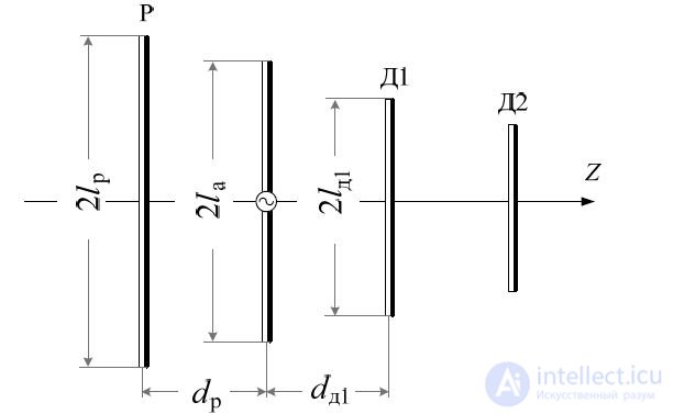
Fig. 8.1 - Director antenna circuit
The amplitude and phase of the current in passive radiators is determined by the distances d di, (
i- director's number, counted from the active emitter side)
and dр from the corresponding passive to active radiator and tuning, which is carried out by changing the length of the arms of the directors and the reflector.
The passive radiator, which has the greatest length (on average (5 ... 10)% longer than the active one), is called a reflector (P), since it reflects energy towards the active radiator and dampens the radiation "backward", that is, in its direction. Passive radiators, the length of which is on average (10 ... 15)% shorter than the length of the active radiator, are called directors (D), since they concentrate the resulting radiation in their direction and quench the radiation towards the active radiator.
The principle of operation of the director antenna is clearly illustrated using vector diagrams. The field emitted by the director antenna in the direction of the positive and negative Z axes is the vectorial sum of the fields of the active radiator, the director and the reflector. The phase shift of the fields emitted by the passive emitters with respect to the active emitter field is determined by the phases of the currents that excite the passive emitters with respect to the phase of the current in the active emitter. When considering the phase relations, it is necessary to take into account that the active emitter has a resonant length, i.e. its input impedance is purely active Ra;
the length of the reflector is more resonant, so its input resistance, along with the active component Rp, has a reactive component Xp, which is inductive in nature; the director's length is less than the resonance one, therefore its input resistance has an active component Rd and a reactive component of capacitive nature Xd. To find the necessary phase relations, it is advisable to use vector diagrams.
Consider the operation of the system of an active symmetric vibrator - a passive reflector under the assumption that 0.15 <= dp / λ> = 0.25. Let us show with the help of vector diagrams (Fig. 8.2, a) that the fields of the emitters in the direction from the reflector to the active symmetric vibrator are added, and in the opposite direction they are subtracted.
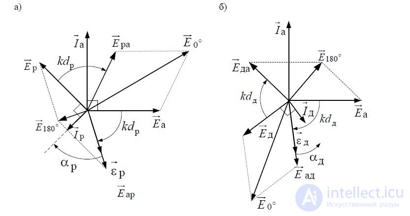
_img_148.jpg) Fig. 8.2 - Vector diagrams for the radiation field of director-type antennas formed by a system of two radiators: a passive reflector and an active radiator (a); passive director and active radiator (b)
Fig. 8.2 - Vector diagrams for the radiation field of director-type antennas formed by a system of two radiators: a passive reflector and an active radiator (a); passive director and active radiator (b)
To determine the electric field strength in the above directions, it is necessary to know how the electric field strength vector Eа of the active symmetric vibrator near its surface and the vector of the electric field intensity of the reflector are displaced in phase relative to each other
near its surface. Set the ratio of the phases by using the vector diagram shown in Fig. 8.2, a. Letvector current
in the active vibrator it occupies a position on the complex plane as shown in fig. 1.3, a. From the theory of antennas it is known that with the length of the arm of a symmetric vibrator 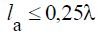 field strength generated by the vibrator on
a distance d in the direction perpendicular to the axis of the radiator (Z axis (see Fig. 8.1)), is determined by the expression
_img_149.jpg)
_img_150.jpg)
_img_151.jpg)

_img_152.jpg) d where d is the distance from the dipole to the observation point; 0 - current antinodes of a symmetrical vibrator; 2
d where d is the distance from the dipole to the observation point; 0 - current antinodes of a symmetrical vibrator; 2
k ; λ is the wavelength of radiation.
In this case, the electric field of the active vibrator at its surface
lags in phase from the current at an angle of π / 2. On the way to the reflector, this field is late in phase by the angle kdp and induces an electromotive force (EMF) on the reflector _img_153.jpg) p, coinciding in phase with
p, coinciding in phase with
_img_154.jpg)
_img_155.jpg)
the electric field at the surface of the reflector Eari defined in accordance with the expression
_img_156.jpg) p
p _img_157.jpg) Ear lр,
Ear lр,
_img_158.jpg)
where Ear is the field of the active symmetric vibrator at the surface of the reflector; -
ldr
the current length of the reflector. Since the reactive input impedance of the reflector is inductive in nature (Xр 0), the current in the reflector _img_159.jpg) I p is late in phase with respect to
I p is late in phase with respect to _img_160.jpg) p at an angle arctg (X / R), where p 0.
p at an angle arctg (X / R), where p 0.
p pp
Electric field strength _img_161.jpg) Ep created at the reflector surface by this
Ep created at the reflector surface by this
_img_162.jpg)
current, lags the outflow of I p in a phase angular π / 2.
On the way to the active vibrator, the reflector field is late in phase by the angle kdri becomes approximately in phase with the field of the active radiator. Therefore, the resultant field in the positive direction of the Z axis _img_163.jpg) E0
E0 _img_164.jpg) Era Ea is increasing.
Era Ea is increasing.
_img_165.jpg)
The fields Far and Ep are approximately antiphasic, therefore the resultant field in the direction of the reflector (negative direction of the Z axis) _img_166.jpg) E180
E180 _img_167.jpg) Far E p is relatively small. With similar reasoning, we can consider the operation of a director antenna,
Far E p is relatively small. With similar reasoning, we can consider the operation of a director antenna,
formed by a passive director and active emitter system. Let the current vector in the active vibrator occupy a position on the complex plane, as shown in Fig.
_img_168.jpg)
_img_169.jpg)
1.3 b. Electric field of an active symmetric vibrator at its surface Ea
_img_170.jpg)
out of phase with current Ia at an angle of π / 2. With its propagation in the direction of the director, the field is late in phase by the angle kdd and induces in the director EMF _img_171.jpg) d, coinciding in phase
d, coinciding in phase
_img_172.jpg)
with an electric field at the surface of director Ed. Since the reactance of the director is capacitive in nature (Xр 0), the current in the director _img_173.jpg) I d is ahead in phase
I d is ahead in phase _img_174.jpg) d
d
_img_175.jpg)
at an angle αd arctg (Xd / Rd), where αd <0. The electric field strength Ed generated by
_img_176.jpg)
director surface current I d, lags behind this current in phase by the angle π / 2. On the way to the active vibrator, the director's field lags in phase by the angle kdd and becomes approximately opposite to the phase of the active symmetric vibrator. Therefore, the resulting field _img_177.jpg) E180
E180 _img_178.jpg) Eda ослаб Ea weakens *** in the direction from director to
Eda ослаб Ea weakens *** in the direction from director to
_img_179.jpg)
active emitter. Fields Ed and Ed are approximately in phase, therefore the resultant
field _img_180.jpg) E0
E0 _img_181.jpg) Ed усили Ed is amplified in the direction of the emitter to the director.
Ed усили Ed is amplified in the direction of the emitter to the director.
8.2. Log periodic antenna
Wide-range log-periodic antennas are constructed based on the principle of electrodynamic similarity, according to which two antennas at waves 1 and 2 have the same electrical characteristics if all their geometrical dimensions are proportional to the ratio of wavelengths 1
_img_182.jpg) 2. In this case, the conductivity of the environment and the material from which both antennas are made should be changed in accordance with the same ratio. The last requirement when making antennas made of metal with high specific conductivity and when placing antennas in the air is not decisive and may not be met. Principles of electrodynamic similarity satisfy antennas of infinite dimensions, the shape of which is completely determined by the angles. In order to create practically feasible antennas, frequency-independent structures must have the “terminal cut-off current” property. This property assumes that at each given wave current flows within a limited area of a frequency-independent structure, the size of which is determined by the wavelength. Outside this part of the structure (called the active region of the antenna), the current decays rapidly (clipped). To explain this phenomenon, one should refer to the conclusions of the theory of excitation of periodic structures. As you know, when a periodic structure is excited, there are two possible modes of operation: in the first, an electromagnetic wave propagates without radiation, and in the second, radiation of electromagnetic waves is observed into the surrounding space. The mode of operation of a periodic structure is determined by the ratio between the phase coefficient of the supply wave propagating along the structure and the period of the structure. With a short period compared with the wavelength, there is no radiation. When the structure period coincides with the wavelength, intense resonance radiation occurs. If resonance radiation occurs in a periodic structure, the energy of the supply wave at the final segment of the structure is almost completely converted into the energy of radiated electromagnetic waves. In this case, the excitation of the structure beyond the radiation region decreases sharply, and the break of the structure does not violate the mode of its operation. The structure period of the periodic-periodic antenna is variable, gradually increasing in the direction from the antenna's power points. Therefore, the current cut-off in these antennas can be explained by the fact that for any wave (in the case of an infinite structure) there is always such a limited region of the antenna, within which the ratio between the structure period and the length of the feeding wave corresponds to the intense radiation mode. A frequency-independent antenna, therefore, is such an antenna of finite size, which in a certain range of waves dominates all the properties of endless antennas. The maximum wave of its operating range is determined by the maximum size of the antenna, and the minimum wave is determined by the accuracy of the structure near the power points of the antenna. An example of a flat log periodic structure is shown in Fig. 8.3.
2. In this case, the conductivity of the environment and the material from which both antennas are made should be changed in accordance with the same ratio. The last requirement when making antennas made of metal with high specific conductivity and when placing antennas in the air is not decisive and may not be met. Principles of electrodynamic similarity satisfy antennas of infinite dimensions, the shape of which is completely determined by the angles. In order to create practically feasible antennas, frequency-independent structures must have the “terminal cut-off current” property. This property assumes that at each given wave current flows within a limited area of a frequency-independent structure, the size of which is determined by the wavelength. Outside this part of the structure (called the active region of the antenna), the current decays rapidly (clipped). To explain this phenomenon, one should refer to the conclusions of the theory of excitation of periodic structures. As you know, when a periodic structure is excited, there are two possible modes of operation: in the first, an electromagnetic wave propagates without radiation, and in the second, radiation of electromagnetic waves is observed into the surrounding space. The mode of operation of a periodic structure is determined by the ratio between the phase coefficient of the supply wave propagating along the structure and the period of the structure. With a short period compared with the wavelength, there is no radiation. When the structure period coincides with the wavelength, intense resonance radiation occurs. If resonance radiation occurs in a periodic structure, the energy of the supply wave at the final segment of the structure is almost completely converted into the energy of radiated electromagnetic waves. In this case, the excitation of the structure beyond the radiation region decreases sharply, and the break of the structure does not violate the mode of its operation. The structure period of the periodic-periodic antenna is variable, gradually increasing in the direction from the antenna's power points. Therefore, the current cut-off in these antennas can be explained by the fact that for any wave (in the case of an infinite structure) there is always such a limited region of the antenna, within which the ratio between the structure period and the length of the feeding wave corresponds to the intense radiation mode. A frequency-independent antenna, therefore, is such an antenna of finite size, which in a certain range of waves dominates all the properties of endless antennas. The maximum wave of its operating range is determined by the maximum size of the antenna, and the minimum wave is determined by the accuracy of the structure near the power points of the antenna. An example of a flat log periodic structure is shown in Fig. 8.3.
A log-periodic antenna (LPA) is a collection of elements whose dimensions form a geometric progression with the denominator:
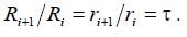 . It is obvious that the change in all sizes of the infinite structure by τ times
will result in a structure whose shape completely coincides with the original one. Therefore, the electrical characteristics of a log-periodic antenna are repeated only at frequencies that form the geometric progression with the denominator 

_img_185.jpg) Fig. 8.3 - Flat log periodic structure
Fig. 8.3 - Flat log periodic structure
When depicted on a frequency scale with a logarithmic scale, these frequencies form a periodic sequence with a constant period equal to ln , which is exactly what the name of this type of antenna is. Obviously, within a single period of change
n n1
frequencies from f0 to f0, the electrical characteristics of the log-periodic antennas will vary. An indispensable condition under which a practically feasible antenna can be considered frequency-independent is a sufficiently small change in its electrical characteristics within one frequency change period. This condition is true for such a constructive execution of a frequency-independent structure, in which one period of frequency change is small. It should be noted that the implementation of antennas in the video structures, as shown in Fig. 8.3, is an additional guarantee of small changes in the electrical characteristics of the antenna within one frequency change period.
The constancy of the input impedance of the antenna is explained as follows. Short vibrators located between the feed point and the active area are weakly excited, and their effect reduces to some change in the equivalent wave
the resistance of the supply line and the change in phase velocity in it. Vibrators of the active area are located at a distance of _img_186.jpg) 4 from each other, and the reflected waves to a large extent mutually compensate each other. In addition, the electrical distance from
4 from each other, and the reflected waves to a large extent mutually compensate each other. In addition, the electrical distance from
the power points to the active area are constant, so the equivalent resistance recalculated to the antenna input does not change with frequency.
The described principle of the ALP is preserved even if both halves of the structure form a certain angle , and the radiating elements have a trapezoidal shape.
In order to fulfill the principle of electrodynamic similarity, the thickness of the protrusions of the antenna would also have to increase in proportion to the distance R; However, experience shows that for the values of the overlap coefficients up to 20, the constancy of the thickness of the radiating elements is practically insignificant.
The parameter also determines the frequency frequency of the characteristics of the antenna, since
fi
, (8.1)
fi1
где fi и fi1 — частоты, соответствующие резонансам i-го и (i+1)-го выступов соответственно (i-й выступ резонирует вместе с таким же выступом второго полотна, когда егодлина оказывается близкой к четверти длины волны). Чем меньше , тем меньше количество зубцов в антенне при заданном R1. Величина может лежать впределахот 0,5 до0,9. Питание плоской логопериодической структуры может быть осуществлено с помощью коаксиального кабеля. Однако согласование при этом получается не оченьхорошим, так как входное сопротивление антеннывелико. Основными параметрами одного полотна проволочной антенны с трапецеидальными выступами являются иугол . Центр излучения одного логопериодического полотна находится в пределах ее активной области и, следовательно, с изменением длины волны перемещается по антенне;однако его относительное расстояние от вершины (выраженное в длинах волн) остается для даннойсистемы постоянным. При углах , не превышающих 60°, величинапараметра почти не влияет на положение фазового центра. Уменьшение угла , естественно, ведет к увеличению расстояния между центром излучения и вершинойструктуры. В современной технике существует логопериодическая антенна «Rohde & Schwarz HL223» (рис. 8.4).
_img_187.jpg)
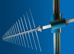
Рис.8.4 — Логопериодическаяантенна «Rohde & Schwarz HL223»
Диаграмма направленности широкополосной антенны Rohde & Schwarz HL223 практически не меняется в зависимости от частоты. Прочная конструкция позволяет использовать антенну,как в стационарных, так и в мобильных применениях. Антенна идеальноподходиткакдля передачиирадиомониторинга, так и дляизмерений.
Одним из видов логопериодических антенн являются направленные антенны. Рассмотрим направленнуюлогопериодическуюантенну"Rohde & Schwarz HL050"(рис. 8.5).
_img_188.jpg)
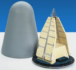
Рис.8.5 — Направленная логопериодическаяантенна "Rohde & Schwarz HL050"
Благодаря широкому диапазону частот от 850 МГц до 26,5 ГГц логопериодическая антенна Rohde & Schwarz HL050 особенно хорошо подходит для радиомониторинга и измеренияпараметров радиочастотных сигналов. Ее диаграмма направленности является практически вращательно-симметричной и обеспечивает формирование оптимальной диаграммы вторичногоизлучения при использовании данной антенны в качестве облучателя зеркальных антенн. Rohde & Schwarz HL050 может использоваться в качестве отдельной антенны или в качестве облучателямикроволновой антенны AC008. Антенна Rohde & Schwarz HL050 обладает аналогичной конструкцией и может использоваться в качестве облучателязеркальных СВЧ антенн AC090 — AC300.

Comments
To leave a comment
Microwave Devices and Antennas
Terms: Microwave Devices and Antennas