Lecture
6. Symmetrical vibrator. The radiation field of the Hertz dipole and symmetrical vibrator. Directional pattern. Radiation power and radiation resistance and radiation resistance of a symmetric vibrator, its input resistance and effective length.
Symmetrical vibrator. The radiation field of the Hertz dipole and symmetrical vibrator. Directional pattern. Radiation power and radiation resistance and radiation resistance of a symmetric vibrator, its input resistance and effective length.
Consider an approximate model of a symmetric vibrator.
Symmetrical vibrator is the simplest and at the same time the most common resonant device among antennas. It serves as a source element for many of their types, as well as a sample in evaluating their gain. Therefore, before proceeding to the characteristics and principle of operation of antennas, it is necessary to become familiar with the theory of a symmetric vibrator (dipole). The term "dipole" is translated as "bipolar" and means that the half-wave radiator is cut in its geometric middle. By forming two "poles", or clamping, connect the feeder from the transmitter or receiver (see. Fig. 6.1).
Any long conductor of electric current, be it a wire, a rod, or a tube, is characterized by well-defined inductance and capacitance values uniformly distributed along its length. This is explained in fig. 6.2, a, where the inductances L1 - L7 with their capacities and capacitances C1 - C4, distributed between the sections of the conductor, are presented.

Fig. 6.1 - Symmetrical Power Vibrator Model

Fig. 6.2 - Current distribution in a half-wave conductor
Let all tanks be charged at a certain moment, that is, they will gain potential. After
so they will begin to discharge through their inductance, as a result, a current will appear and a corresponding magnetic field will appear.
When the capacitance C4 is discharged, a current I4 flows through the inductance L4;
The NW will be discharged through L3, L4 and L5 when current flows 3;
C2 through L2 - L6 will cause current I2.
Finally, C1 is discharged through L1 - L7 at a current I1.
It follows that the highest current, equal to the sum of the currents of the range I1 - I4, will flow in the middle part of the radiator;
the current will decrease to its ends, where it will vanish.
For the sake of greater clarity, currents I1 - I4 are presented in Fig. 6.2, b in another form. Under the action of current around inductances magnetic fields are formed.
They will again inform the capacitors of charges of opposite polarity, so the sign of the voltage will change.
Now the process will be repeated, but in the opposite direction shown in Fig. 6.2, bs using currents I1 - I4. With all the simplifications, the picture shown in fig. 6.2, gives an idea of the resonant current distribution and
voltage in a half-wave radiator.
The voltage and current are shifted in phase by 90 °, while the phase difference of the voltages at the ends of the radiator is 180 °.
If we refine all approximations, then we use the equations of a long line of length l and transfer the frame of reference to
connection point of the input terminals. Then the system of equations will look like:

From the distribution of current and voltage in a half-wave radiator, it follows that in its middle part the current is maximum (current antinode),
and the voltage is zero (voltage node). At the ends of the radiator, the relations are opposite: the voltage antinode coincides with the current node.
It is also clear from the voltage distribution that the half-wave elements can be geometrically attached with a conductive bracket directly to the grounded antenna support, since the fixture at the point of zero voltage does not require insulation.
Therefore, the half-wave elements allow ground *** *** in the geometric center. But then the voltage in the middle of the radiator turns out to be slightly different from zero. The same happens with the current tips of the radiator, where it does not reach zero due to the end effect.
So it would be more accurate to talk about current and voltage minima.
As can be seen from fig. 6.2, in, the current is always maximum in the middle of the half-wave vibrator, which is in a state of its own resonance.
The current is reduced by the sine wave to the ends of the vibrator, where it vanishes. Here there is a maximum voltage
sinusoidally decreasing to the middle of the vibrator. There it becomes so small that in the first approximation it can be taken equal to zero.
Strictly speaking, the voltages and currents are not quite sinusoidally distributed across the vibrator.
Consider examples. Hertz's dipole,
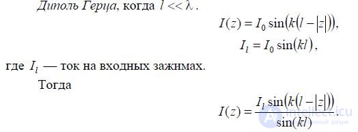
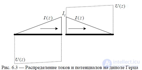
The current distribution has the form, as shown in fig. 6.3.
_img_113.jpg)
Half wave vibrator when  .
.
The current distribution has the form, as shown in fig. 6.4.
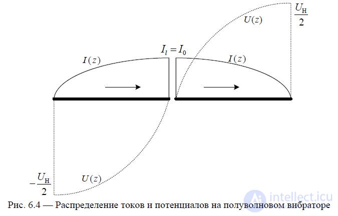
Fig. 6.4 —Distribution of currents and potentials on a half-wave vibrator
The currents on both shoulders are in phase, which is favorable from the point of view of the formation of directional radiation.
Wave vibrator when 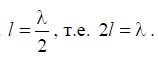 .
.
The current distribution has the form, as shown in fig. 6.5.
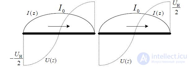
Fig. 6.5 - Distribution of currents and potentials on a wave vibrator
Wave vibrator works like two half-wave vibrators.
Symmetrical long arm vibrator 
The current distribution has the form, as shown in fig. 6.6.
_img_117.jpg)
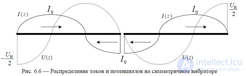
With  on any symmetric vibrator appear the opposite phase of the current,
2 which do not *** aggravally affect the characteristics of the radiation, when the intensity of the radiation decreases towards the main maximum.
In this case, the radiated power is redistributed in lateral directions.
Symmetrical vibrator with long shoulders l l. The current distribution has the form, as shown in fig. 6.7.

Fig. 6.7 - Distribution of currents and potentials on a symmetrical vibrator
Since the in-phase and anti-phase currents are equal, there is no radiation in the main direction.
A strict solution of the problem of current distribution shows that the current in the nodes is somewhat different from zero. This is due to the fact that the vibrator, in contrast to the two-wire line, emits.
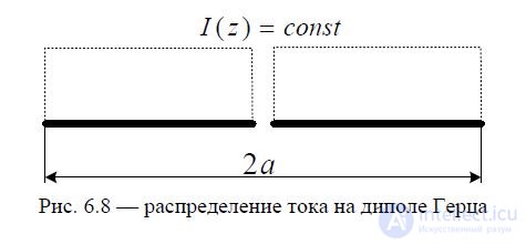
Consider the Hertz dipole and the current distribution on it (see Fig. 6.8).
For the analysis of the radiation field of the antenna there are several main radiation zones.
The induction zone or the near zone (Fresnel zone) of an elementary radiator is an area of space where, in the expressions for E and H, terms proportional to 1 / r ^ 2 and 1 / r ^ 3 are dominated by sublemes proportional to 1 / r. The emitted electromagnetic field in the Fresnel zone has a vortex character.
The radiation zone (Fraunhofer zone), the wave zone or the far zone of an elementary radiator is an area of space in which the dominant are terms proportional to 1 / r. The radiated electromagnetic field in the far field is a spherical wave in which the electric and magnetic vectors are perpendicular to the propagation direction, i.e. is a transverse electromagnetic wave.
Consider the vertical Hertz dipole located in the Cartesian coordinate system (see fig. 6.9).
_img_121.jpg)
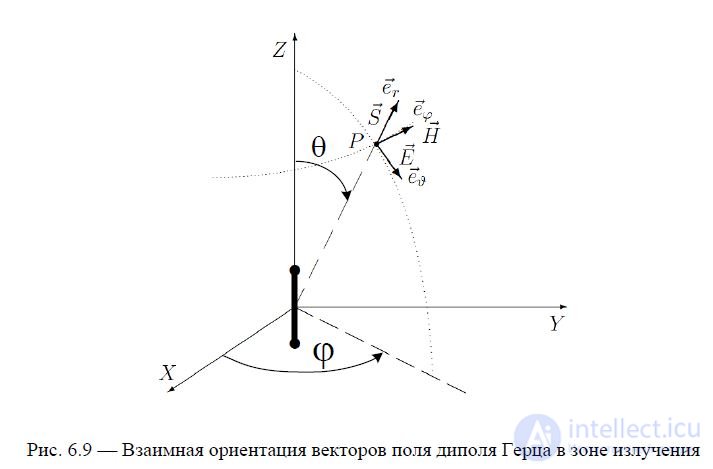
Figure 6.9 shows the mutual orientation of the Hertz electric dipole field vectors in the radiation zone. It should be noted that for the Hertz dipole, the strength vector of the electrical field at any point (observation point) in the radiation zone is tangential to a circle lying in a plane passing through the observation point and the dipole axis. In particular, in the reviewed example (the dipole axis coincides with the OZ axis of the spherical coordinate system) the vector E at any point of the radiation zone is directed along the orth of eϑ, and the vector H along the orth of eϕ, as shown in fig. 6.9.
The electric dipole field is characterized by three components:  , of which the longitudinal component Er can be neglected, since it is proportional
Field components  related by
Thus, it suffices to investigate only one E component of the radiation field of the Hertz dipole. Omit further index  . The electric transverse component of the field is determined by the expression
where r is the distance to the observation point located in the far zone. The amplitude of the electric dipole field is determined by the expression
The amplitude does not depend on the angle , i.e. the radiation field of the Hertz dipole has
EDH
axial symmetry. When 0, there is no radiation, i.e. in the axial direction, the dipole does not radiate.
At , the maximum radiation field is observed — the direction orthogonal to the 2 axis of the dipole — the main direction.
Directional pattern definition.
The radiation pattern of the transmitting antenna across the field is a graphical representation of the dependence of the modulus of the complex amplitude of the electric vector component of the electromagnetic field generated by the antenna in the far zone on the angular coordinates θ and φ of the observation point in the horizontal and vertical planes, i.e. E (θ, φ ).
It is customary to denote the DN by the function f (θ, φ). DNs are normalized - all values of E (θ, φ) are divided by the maximum value of Emax and denoted normalized DN by the function F (θ, φ).
Any antenna has a certain directivity described by the corresponding diagram. To accurately display the directivity, it is necessary to construct its three-dimensional (spatial) image. But the spatial distribution of density is difficult to depict graphically, therefore, they are usually content with the representation of the directional pattern in the vertical and horizontal planes (in the main sections).
The antenna pattern can be depicted in the polar coordinate system or in the cross section of this system, as well as in Cartesian (rectangular) coordinates.
In polar coordinates, a grid of concentric circles and rays emanating from their center is used (Fig. 6.10). Concentric circles represent voltage, and in their center it is equal to zero.
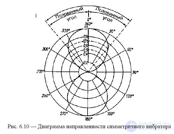
Fig. 6.10 - Symmetrical vibrator pattern
In fig. 6.10 shows the normalized radiation pattern of a half-wave vibrator in the horizontal
the plane (the plane E, the width of the beam DN across the field, determined by the level of 0.707 from the maximum, is 80 °).
The radiation pattern determines a number of important parameters of the antenna under consideration. The half width of the main lobe is called the half-level angle. This is the angle between the maximum radiation direction and the direction where the energy flux density is half the maximum. To determine this angle, the point of greatest stress in the main direction is assigned a value of 1.0 and on both sides of the radiation lobe there are points at which the voltage is 0.707 of the maximum. A decrease in voltage of 0.707 times corresponds to a power reduction of 50% or 3 dB. Then, as shown in fig. 6.10, through these points there are straight lines from the center, which serve as the sides of the desired angle of the half-level. Usually prefer to use the concept of the width of the diagram at half power or width at the level of 3 dB. The width of the lobe of the radiation pattern of half the power is equal to the sum of both angles of the half level and denotes the interval of angles in which the energy flux density is at least half of its maximum value.
The point of the radiation pattern, where the voltage decreases to zero, is called zero. Its position is described by the zero angle, that is, the angle between the direction of maximum radiation and the direction to the first zero point. The width at the zero level is the interval of angles between the first zero points on either side of the main petal of the direction pattern.
The directivity pattern is normalized when all voltage values are divided by its maximum value and the result of the division is expressed in fractions of a unit or percentage.
To describe the position of the planes in which radiation patterns are constructed, the concepts of the Ε plane and the H plane are used. The first one corresponds to the direction of the electric field line in a plane wave front, the second to the direction of the magnetic field lines (see Fig. 6.9).
In accordance with (6.3), the pattern of the hertz dipole is described by the function
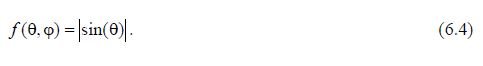
In the E-plane, the DN, constructed according to (7.3) has the form, as shown in Fig. 6.11 - in blue.
Since, for the Hertz dipole, f (, ) does not depend on , in the H-plane the direction diagram has the form, as shown in Fig. 6.11 in red - DN circular.

Fig. 6.11 - Directional diagrams of the Hertz dipole in the main sections
Obtained in fig. 6.11 radiation patterns of the emitter allow you to restore the three-dimensional DN dipole
Hertz, which has the form, as shown in section in Fig. 6.12.
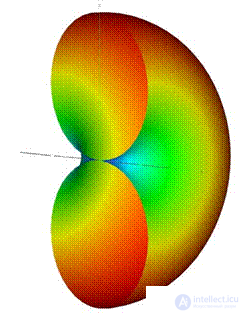
Fig. 6.12 - Section of a three-dimensional DN Hertz dipole
The power pattern can be found if the intensity of the field radiation at the receiving point is known, which is determined by the size of the Poynting vector.
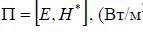
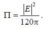
Thus, the power pattern fM , is determined from the radiation pattern by the field f , based on the ratio
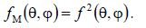
In the Cartesian system of coordinates, the DNs of the Hertz dipole in the field and in power have the form, as shown in Fig. 6.13.
_img_125.jpg)
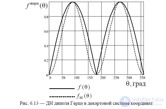
Fig. 6.13 - DN of Hertz dipole in Cartesian coordinate system
Mentally divide the vibrator into an infinitely large number of elements dz. Since the length of each element is infinitely small, it can be assumed that, within its limits, its current does not change either amplitude or phase. Thus, the entire vibrator can be considered as a set of elementary electric vibrators dz and, accordingly, the field of the vibrator in question can be represented as the result of the addition (interference) of the fields emitted by the elementary vibrators. Due to the smallness of the air gap (gap) between the vibrator arms, the influence of the electric field (magnetic current) existing in it on the radiation can be ignored and the electric current flows through a solid conductor 2l in length.
Select an element with a length dz on the vibrator at the point z and determine the field created by this element at an arbitrary observation point M located at a distance r0 from the center-vibrator (in the radiation zone for all elementary vibrators) at an angle to its axis (Fig. 6.14).
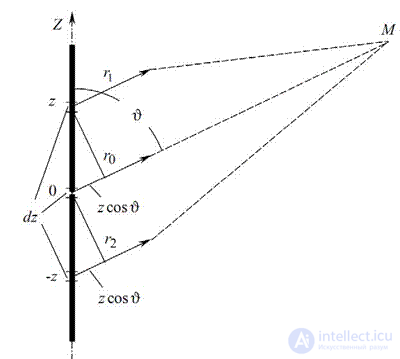
Fig. 6.14 - To the determination of the radiation field of a symmetric vibrator
Due to the small size of the element, we can assume that the current in it is unchanged in length and has a complex amplitude I (z). In this case, the distance from the element to the point M is equal to r1. The considered element can be considered an elementary radiator - Hertz dipole, therefore the field created by, according to (6.3), will be determined by the expression

where I (z) is the complex current on the elementary radiator. Find the value of r1. As can be seen from fig. 6.5,
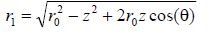
We use the well-known approximate expression 1+ x ≈1 + x / 2 - x2 / 8, true for x <1. Taking out in (6.5) the value of r0 from under the root and leaving the terms containing z to a degree not lower than 2, we get
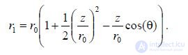
If the point M is sufficiently far from the vibrator, then all the rays connecting the antenna points with the point M, are almost parallel. Let us lower from point z in fig. 6.14 perpendicular to the direction of r0. As a result, for r1 we obtain the ratio

Thus, it is possible to define the far zone of the antenna as an area of space, for each point of which all the rays going from the antenna to this point are parallel. The r z cos () value is often called the path difference of the rays coming from the center of the vibrator and from the point with z coordinate. Since the observation point is far away from
vibrator, the Δr value is small compared to r0 and the distances r0 and r1 differ little from each other. Based on (6.6), we obtain the expression for the phase factor in (6.5)
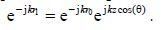
After conversion (6.5) we get the expression

The final expression for the radiation field of a symmetric vibrator

В r0 sin() Как и в случае диполя Герца, формула (6.7) состоит из трёх множителей: множителя, определяющего только величину напряжённостиполя и не зависящего от направления на
60I0
данную точку А множителя, определяющего направленные свойства (характеристика r0 направленности)
и фазового множителя je jkr . Из (6.8) видно, что симметричный вибратор обладает направленными свойствами только в плоскости E, причём эти свойства определяютсятолько отношением длины плеча вибратора кдлине волны l/λ.
Анализ ДН симметричного вибратора проведем на основании формулы (6.8).
Из (6.9) видно, что симметричный вибратор обладает направленными свойствами только в плоскости E, причём эти свойства определяются только отношением длины плеча вибраторакдлине волны l/λ.
Вдоль оси (в направлении 0) провод с током не излучает. Рассмотрим несколько случаев:
- диполь Герца, когда l1 ;
- симметричный вибратор с длиной плеч 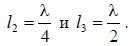
Результаты расчетов диаграмм направленности в Е-плоскости по формуле (6.9) представлены на рис. 6.15.
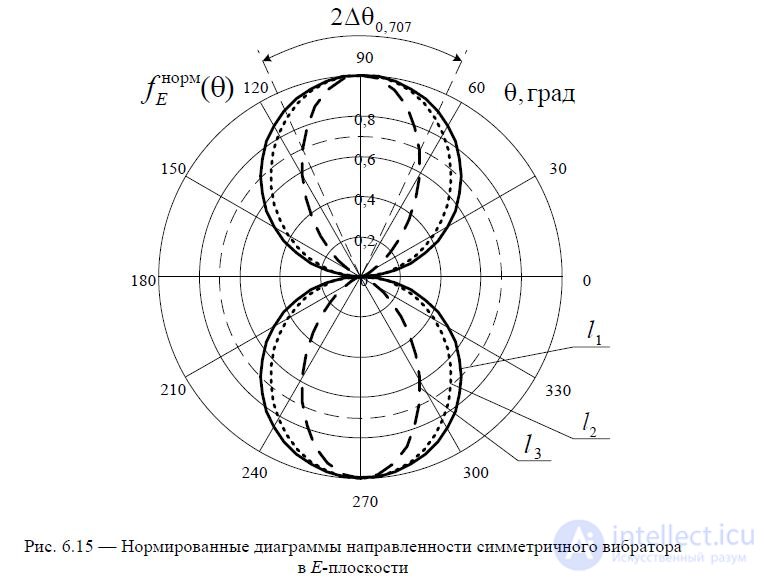
Ширина диаграммы направленности определяется, как показано на рис. 6.15.
Если длина плеча симметричного вибратора l , то в направлении,
2 перпендикулярном оси вибратора, т.е. в экваториальной плоскости ( 90 , 270 ), поля всех элементарных излучателейсинфазны, и, следовательно, поле в данном направлении является
максимальным. Увеличение длины вибратора до значения l сопровождается ростом
2 излучения в направлении, перпендикулярном оси вибратора (главное направление излучения) за счёт уменьшения излученияв других направлениях. При этом ДН становится уже (рис. 6.15).
Рассмотрим еще несколько случаев: симметричные вибраторы с длиной плеч l4 0,625 , l5 0,75 и l6 . Результаты расчетов представлены на рис. 6.16.
l
При увеличении 0,5 характеристика направленности проходит через 0 не только
при 0 ,180 , но и при некоторых других значениях этого угла. Главные лепестки становятся уже, но появляются боковые лепестки, излучение в главномнаправлении
уменьшается. Уменьшение излучения в главном направлении объясняется следующим: результирующий сдвиг фаз полей, излучаемых элементарными излучателями в данном направлении,определяется пространственным сдвигом фаз и сдвигом фаз токов этих
l
элементарных излучателей. При 0,5 на вибраторе появляются участки с
l
противофазными токами, длина которых растёт по мере увеличения отношения . therefore
в данном случае, хотя в главном направлении пространственные сдвиги фаз равны нулю, поля, излучаемыенесинфазными токами элементарных излучателей, складываются несинфазно.

Fig. 6.16 — Нормированные диаграммы направленности симметричного вибратора в Е -плоскости
Рост отношения  сопровождается также ростом боковых лепестков, и при
напряжённость поля в направлении максимума бокового лепестка становится равной
l
напряжённости поля в главном направлении, а при дальнейшем увеличении превосходит
её.
ll
При 1 (или при n , где n — целое число) излучение в главном направлении
отсутствует, т.к. противофазные участки вибратора имеют одинаковуюдлину.
l
На практике применяются симметричные вибраторы, у которых 0,7 и максимум
излучения совпадает с главным направлением ( 90 , 270 ).
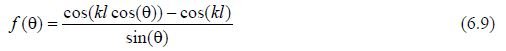
В дальнейшем будем рассматривать именно такиевибраторы. Нормированная диаграмма направленности такого
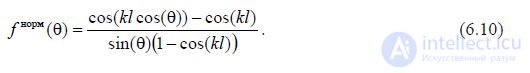
вибратора, описываетсявыражением
Мощность P, излучаемую симметричным вибратором, можно найти методом вектора Пойнтинга, т.е. интегрированием среднего значения вектора Пойнтинга по поверхности сферыбольшого радиуса (в дальней зоне), в центре которой находится вибратор. Так же, как и в случае диполя Герца, можно записать
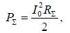
где R — сопротивление излучения, отнесенное к току в пучности. l
При длине плеча 0,25 сопротивление излучения пересчитывается на входные
зажимы антенны по формуле
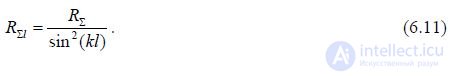
В общем случае сопротивление излучения, отнесенное к пучности тока определяется по формуле
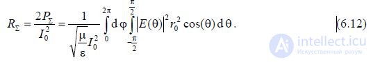
Подставляя в (6.12) выражение для характеристики направленности (6.8) (без фазовых множителей), получаем
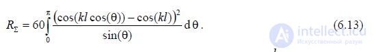
Как видно из (6.13), величина Rзависит только от отношения . Эта формула
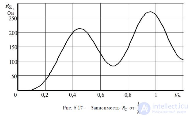
является приближенной, поскольку она выведена для синусоидального распределения тока по вибратору, чтосправедливо только для очень тонких вибраторов. Однако результаты расчётов по (6.13) хорошо совпадают с экспериментальными данными. Это объясняется тем, что сопротивление излученияопределяется полем в дальней зоне, которое мало зависит от толщины вибратора. In fig. 6.17 показан график рассчитанной по (6.13) зависимости Rот
l
. Осциллирующий характер зависимости объясняется тем, что интерференционная картина
l
поля в дальнейзоне меняется при изменении отношения .
Далее определим входное сопротивление симметричного вибратора. Мощности, излученной вибратором (или любой антенной), соответствует активное сопротивление излучения.Мощности потерь соответствует активное сопротивление потерь. Наряду с излученным электромагнитным полем существует колеблющееся вблизи антенны и связанное с ней электромагнитноеполе, которому соответствует реактивная мощность. Последнейсоответствует реактивное сопротивление антенны.
Таким образом подключенный к антенне генератор нагружен на комплексное сопротивление, называемое входным сопротивлением антенны. Входное сопротивление симметричного вибратора (а также других проволочных антенн) равно отношению напряжения на зажимах вибратора (точки питания) к току в точках питания
_img_131.jpg)
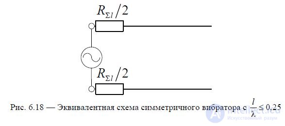
В дальнейшем опустим сопротивление потерь. Для симметричного вибратора с l 0,25 можно воспользоваться приближенной эквивалентной схемой излучателя,
основанной на введение в модель длинной линии сопротивления излучения, отнесенного ко входным зажимам — см. рис. 6.18.
Для разомкнутой линии передачи ее входное сопротивление определяется при x l ис учетом включенного в линию сопротивления излучения входное сопротивление
l
симметричного вибратора с 0,25 можно приближенно рассчитать по формуле

где Rl , а Rопределяется по графику на рис. 6.17.
sin2(kl) l
Для симметричного вибратора с 0,25 можно воспользоваться приближенной
эквивалентной схемой излучателя, основанной на введение в модель длинной линии
сопротивления излучения, включенного в точке пучности тока, которая отстоит от концов
плеч излучателя на расстоянии — см. рис. 6.19, а.
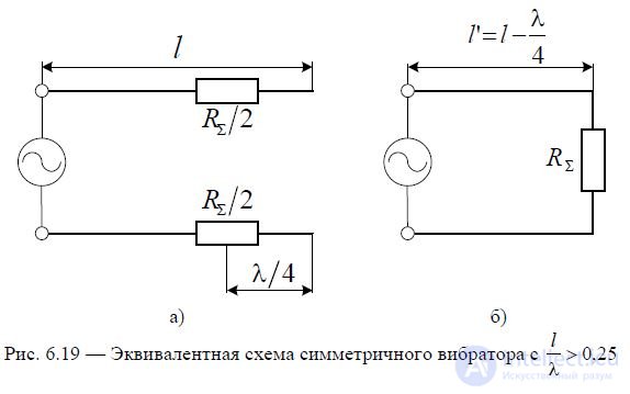
Зная свойство разомкнутого отрезка линии длиной можно перейти к эквивалентной
4 схеме симметричного вибратора, представленной на рис. 6.19, б. Тогда входное сопротивлениесимметричного вибратора можно определить по формуле
где волновое сопротивление симметричного вибратора определяется по формуле
l
120ln1 ; a — радиус проводника; значение коэффициента бегущих волн В a
_img_136.jpg)
определяется по формуле КБВ RСВ (при R ); отрезок линии l' l .
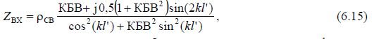
4 На основании (6.15) проведем расчеты входного сопротивления симметричного
l
вибратора как зависимость от — см. рис. 6.20, где представлены графики для активной
(6.20, а) и реактивной (6.20, б) составляющих входного сопротивления при различных значениях волнового сопротивления симметричного вибратора В . Видно, что с
уменьшением В зависимости RВХи X Х сглаживаются. Это имеет существенное значение для согласования антенны с питающей линией. Рассчитаем зависимости КСВ, соответствующиепредставленным на рис. 6.20 графикам входного сопротивления антенны. Результаты расчетов приведены на рис. 6.21. Из рисунка видно, что с уменьшением волнового сопротивлениясимметричного вибратора В расширяется полоса согласования
антенны с питающей линией. Это свойство симметричного вибратора широко применяется на практике. Добиться уменьшения В можно за счет увеличения ширины проводников, образующихплечи симметричного вибратора.
_img_137.jpg)
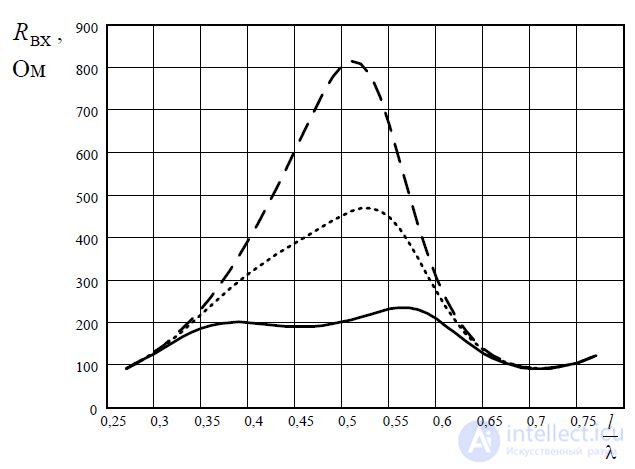
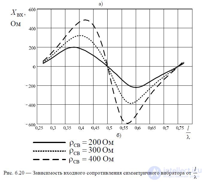
Fig. 6.20 — Зависимость входного сопротивления симметричного вибратора от
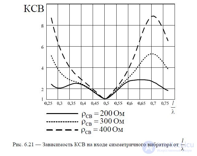
Fig. 6.21 — Зависимость КСВ на входе симметричного вибратора от
Действующая длина антенны. В случае вибраторных антенн иногда удобно пользоваться расчётным параметром, называемым действующей длиной антенны. Действующей длиной lДсимметричного вибратора (или другой антенны) называется длина
воображаемого вибратора с равномерным распределением тока ( I (z) I0 const ),
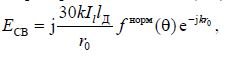
создающего в направлении максимального излучения (при 90 , 270 ) поле, равное полю данной антенны в направлении её максимального излучения. При этом токи в точках питания обеих антенн считаются равными.
Исходя из условия равенства моментов токов определим действующую длину симметричного вибратора
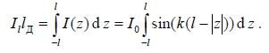
После преобразований получим выражение для определения действующей длины l Д
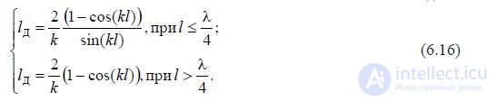
С учетом (6.16) можно записать выражение для нормированной диаграммы направленности симметричного вибратора наосновании (8.4) в виде

Comments
To leave a comment
Microwave Devices and Antennas
Terms: Microwave Devices and Antennas