Lecture
Striped directional couplers with distributed electromagnetic coupling (Fig. 2) are parallel-arranged and electromagnetically coupled strip waveguides with a TEM-type wave. The power branched into the additional strip waveguide propagates in the direction opposite to its propagation direction in the main waveguide. These couplers are called "opposing". Depending on the electrical length of the communication section, directional couplers can be single-link (single-stage) (Fig. 2, a) and multilink (multi-stage) (Fig. 2, b).

Figure 2. Single-link directional coupler with electromagnetic coupling (a) and multi-link (b)
Multi-link couplers allow increased system connectivity and broadband. For example, three-link couplers on symmetric strip waveguides with transitional attenuation at the middle frequency C13 = 3 dB provide the overlap factor kf = f1 / f2 when the coupling deviates from the average value by D С13 = ± 0.4 dB and kf = 3 with C13 = ± 0 , 1 dB.
Single-link couplers provide an overlap factor of kf »2 at C13 = 3 dB and D C13 = ± 0.3 dB. Moreover, the frequency response of the transient attenuation of a single-link coupler has the form of a cosine curve, while the characteristic of multi-link couplers can be made as flat as possible or Chebyshev (with an equal deviation from the mean value). With increasing transition attenuation with fixed values of D C13, the working band of the coupler narrows. The magnitude of the directivity is theoretically ideal (infinite) in an unlimited frequency band. The voltages in the output arms 2 and 4 of the directional coupler do not depend on frequency and have a constant phase shift equal to l / 2.
The most widespread among directional taps with weak electromagnetic coupling are side tied couplers (Fig. 3, a). They are most often performed on the basis of microwave printing methods, both on symmetric and asymmetrical strip waveguides. Among the varieties of directional couplers with a weak coupling, note should be noted of the taps with a diaphragm between parallel-spaced strip waveguides (Fig. 3.b, c). The magnitude of the relationship of this configuration can be adjusted by changing the size of the gap in the diaphragm.
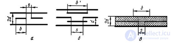
Figure 3 Cross section of strip directional couplers with weak electromagnetic coupling:
a - with side coupling on a symmetric strip waveguide;
b - with connection through a diaphragm on a symmetric strip waveguide;
(c) with coupling through a diaphragm on an asymmetrical strip waveguide with a solid dielectric.
Directional couplers with a strong coupling (small transient attenuation) should include coupling with a so-called facial coupling or with a connection on the wide sides of strip waveguides. In this case, the associated strip waveguides are located either parallel or perpendicular to the grounded plates. Since each strip waveguide is located asymmetrically with respect to external grounded plates, various types of colo- sions are possible in such directional couplers.
However, by completely shielding the coupler or by introducing an additional balancing strip, parasitic collar types *** can be eliminated almost completely.
It should be noted that directional couplers with a strong coupling can also be created when using lateral coupling between strip waveguides (Fig. 3, a). In this case, the thickness of the strip waveguides should be chosen such that the gap between them at a given magnitude of connection is technologically feasible.
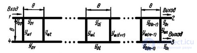
Figure 5. Diagram of n-loop directional coupler
The taps of a stub type consist of two parallel transmitting strip waveguides connected by a series of parallel stubs (Fig. 5). The length of the loops and the distance between them is equal to one quarter of the wavelength (or an odd number of quarters of the waves) in a strip waveguide at a medium frequency. Branched power in the additional channel is distributed in it in the same direction as in the main strip waveguide. The smallest number of loops at which the directional branch of power occurs is two. Depending on the number of loops, this type of directional couplers is subdivided into two, three, and, in general, n-loop couplers. As the number of loops increases, their frequency response improves. The phase shift of the voltages on the output arms 2 and 3 of the coupler is 90 °.
Straight directional couplers are used, as a rule, to obtain a strong coupling when using both symmetric and asymmetrical strip waveguides, since the provision of weak coupling is associated with structural and technological difficulties of making a very small cross-section of the loops.
Directional couplers with capacitive coupling are intended for symmetric strip waveguides at frequencies below 4 GHz (Fig. 6.a). The unwanted inductive coupling of the pins of strip waveguides is weakened *** due to the perpendicular arrangement of the strip waveguides in the places of their connection, where they are separated from each other by a dielectric. The distance between the communication sections is equal to a quarter of the wavelength in a strip waveguide. With an increase in the number of series-connected taps (Fig. 6, b), the directivity increases. The coupling in such directional couplers is chosen sufficiently strong, since the limiting factor in choosing a weaker coupling is proportional decrease in directivity.
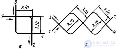
Figure 6. Schemes of a single section (a)
and two-section (b) couplers with capacitive coupling.

Comments
To leave a comment
Microwave Devices and Antennas
Terms: Microwave Devices and Antennas