Lecture
Filters are an integral part of many microwave devices. They are used for the purpose of separating and summing signals with different frequencies in multichannel devices, frequency converters and multipliers, to increase the selectivity of receiving devices, to limit the spectrum of a transmitter, etc.
Such a wide use of filters in the microwave technology has led to a large variety of their schemes and designs. The most widespread are microwave filters obtained from low-pass filters by replacing elements with lumped parameters with elements of microwave devices having the same characteristics in a certain frequency range.
Microwave filters, like lumped filters, are one or N series-connected two-port networks that selectively pass a certain frequency band. Depending on the bandwidth, the filters are divided into the following types:
low-pass filters (low-pass filters) that pass frequencies from zero to the cut-off frequency — f 1 (Figure 4.1, a );
high-pass filters (HPF) that pass frequencies from f 1 to  (Fig. 4.1, b );
bandpass filters (PF), passing a certain frequency band from f - n to f n (Fig. 4.1, c );
fencing (notch) filters (ZF) that do not allow the frequency band from f- z to f g (Fig. 4.1, d ) .
Practically, such ideal frequency characteristics are not feasible, therefore, when designing filters, deviations from these ideal characteristics are specified.
Each filter is characterized by the following parameters:
boundary frequencies of the passband f - n , f n (for low-pass filters and high-pass filters -
cut-off frequency f 1 );
boundary frequencies of the fencing band f- z , f g ;
maximum permissible attenuation in the passband - b n , db;

Fig. 4.1. Ideal frequency response filters:
a - low - pass filter; b - high pass filter; in - PF; d - ZF.
minimum attenuation at the boundaries of the barrier line - b n , dB;
nominal characteristic resistance chosen from design considerations.
Depending on the requirements for the filter, various filter schemes and their various constructive implementation are applied. In band-pass filters, the following link schemes are most common:
three-element scheme (Fig. 4.2, a, T-shaped scheme);
four-element scheme (Fig. 4.2, b, U-shaped scheme}.
The cascade connection of these links forms the overall ladder structure of the filter (Fig. 4.2, c, d ) .
The design task is to ensure the required bandwidth, allowable levels of attenuation in the passband, ensure the required dynamic range, minimum weight and dimensions, maintain performance in degraded climatic conditions, ease of setup and manufacturing, and maximum reliability.
There are two methods for calculating filters:
by characteristic parameters;
by operating parameters.

Fig. 4.2. Filter schemes: a - three - element scheme of the link;
b - four - element scheme of the link; in, d - - ladder schemes of filters three - and four-element respectively.
All calculations on the characteristic parameters are special cases of calculations on the working parameters, and therefore, more simple. The method of calculation for the characteristic parameters is applied in the event that a significant non-uniformity of the characteristic of the frequency attenuation of the filter in the transparency band is allowed. In this case, the filter consists of N identical links. The parameter is the characteristic resistance of the filter, chosen from design considerations and used to determine the elements of the filter circuit. Using the method of characteristic parameters, a three-element scheme is calculated (Fig. 4.2, a, c ) , performed on coaxial lines and received the most practical distribution.
The method of calculation for the operating parameters allows to obtain a given frequency response of the filter with the minimum number of elements, based on the conditions of physical realizability. The following are used as operating parameters: the required bandwidth is f - n > f n ; maximum permissible attenuation in the passband - b n ; minimum permissible attenuation in the stopband - b g . The required frequency characteristic of attenuation is approximated by a physically realizable function, the parameters of which determine the elements of the filter circuit.
There are several ways to approximate:
approximation using the maximally smooth curve described by the Butterworth polynomial,
approximation using Chebyshev polynomials,
approximation using the Jacobi elliptic function.
The most common are the first two methods of approximation.
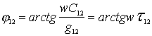
When approximating with the help of a maximally smooth (flat) curve, the frequency response of a bandpass filter has the form shown in Fig. 4.3, a (parabola of 2 nd order). In this case, the frequency response is described by the formula 
Where
 (4.2)
(4.2)
S - scale factor,
 (4.3)
(4.3)
 - frequency variable;
f 0 - average frequency range;
N is the number of links of the filter;
h - amplitude factor;
 (4.4)
(4.4)
G max - the maximum allowable reflection coefficient in the band f - n > f n associated with the maximum allowable loss in the passband by the formula

Fig. 4.3. The frequency characteristics of polynomial band - pass filters: a - as smooth as possible; b - Chebyshev.
 (4.5)
(4.5)
When approximating using Chebyshev polynomials, the frequency response has the form shown in Fig . 4.3, b. In this case, the frequency response is described by the formula
 (4.6)
(4.6)
Where  - Chebyshev polynomial of the 1st kind, of the Nth order, (2.9) - (2.12);
N is the number of links of the filter.
Chebyshev filters have steeper slopes of frequency response than filters with the smoothest response. The choice of one or another type of frequency response is determined by the specified filter requirements. For the selected type of frequency response and given f - n , f n , f - c , f c , b n , b c , the number of links of the filter N is determined .
For a bandpass filter, the number of links is determined by the formulas:
for the smoothest possible filter
 (4.7)
(4.7)
where L C , L p - gear ratios, determined from the formulas
for Chebyshev filter  (4.8)
(4.8)
The next step in the synthesis is to determine the numerical values of the elements of the filter circuit. To simplify the calculation method for the operating parameters, a normalized calculation is used, that is, for the “prototype” - a low-pass filter (Fig. 4.4), from which you can get the circuit elements of the projected filter.
The elements of the “prototype” low-pass filter for filters with the smoothest characteristic are determined by the formula
 (4.9)
(4.9)
For a filter with a Chebyshev form, the characteristics of the elements of the prototype are determined from the following expressions:
1) for odd  ,
,
for even  ,
,
2) 
where b n - the maximum permissible ripple in the passband of the filter, db (Fig. 4.3);

Fig. 4.4. The prototype low-pass filter for even and odd N.
3) 
four) 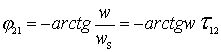
five)  (4.10)
6) 
7) 
The above formulas are derived under the following assumptions:
1. The load resistance on the left side of the circuit is 1 Ohm.
2 The first element g 1 is the shunt capacitance in farads, the successive elements are the inductance in Henry.
3. The resistance r on the right side of the circuit is 1 Ohm for all cases considered. The exceptions are Chebyshev filters with even N.
The elements of the schemes of other filters are determined through the known elements of the prototype by the appropriate transformations. The formulas for these conversions are designed for specific schemes.
After calculating the filter elements, the task of its implementation with the help of microwave elements remains. Methods for implementing filters using microwave elements will be covered in the following sections when considering typical filter designs.

Comments
To leave a comment
Microwave Devices and Antennas
Terms: Microwave Devices and Antennas