Lecture
Coaxial filters are spread in the meter, decimeter and long wavelengths of the centimeter (more than 5 cm ) radio wave bands. The most common filters on short intervals.
In filters on short segments of transmission lines, the equivalence property of short segments of lines is used (  ), loaded on resistance several times smaller than the wave - series inductance, and short segments of transmission lines, loaded on a resistance greater than the wave - parallel capacitance.
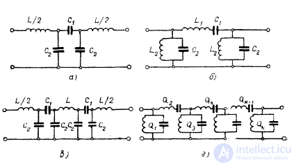
Filters on short segments are performed according to the three-element scheme of the link (Fig. 4.2, a, c).
The calculation of coaxial filters is performed by the method of characteristic parameters, that is, the characteristic resistance of the filter is selected from the condition of the structural implementation of the elements, the elements of the filter circuit and the geometric dimensions are determined.
Low-pass filters on short segments consist of series-connected segments of transmission lines with high and low characteristic impedances. Structurally, the low-pass filter is a rigid coaxial line, the outer conductor of which is made of brass pipe with a diameter D (Fig. 4.5). The inner conductor of the filter operating in the centimeter wavelength range is a brass rod consisting of segments of different diameters d 1 and d 2 (Fig. 4.5, a); in the decimeter and meter wave ranges, the segments of the conductor with a smaller diameter are replaced by spiral lines (Fig. 4.5, b).
The framework of the helix line and the dielectric bushing between the inner and outer conductors of the coaxial line (parallel capacitance) are made of high-frequency dielectrics with low losses such as PT, polystyrene, fluoroplast-4, etc. a low-pass type K filter circuit assembled according to a T or U-shaped pattern (Fig. 4.5, c, d).
Shown in fig. 4.5, and the filter has a T-shaped scheme of links. Segments of lines of length l 1 , with a large characteristic impedance  (Fig. 4.5, a), and spiral lines (Fig. 4.5, b) are equivalent to concentrated inductances, segments of a line of length l 2 with a low characteristic impedance
  - to containers.
The laws of variation of the characteristic resistances for T-and U-shaped filters are different and are shown in fig. 4.5, in,
In order to ensure the best matching of Z har filter with load resistance Z n in the frequency range from 0 to f 1, it is necessary that Z о be equal to:
for the T-link Z 0 " 1.41 Z n , (4.11)
for the U-shaped link Z 0 " Z n / 1.41. (4.12)

Fig. 4.5. Low-pass filter: a - lowpass filter centimeter will;
b — FNC decimeter and meter waves; (c) Zhar dependence on frequency for the T-shaped circuit; d - for the U-shaped scheme.
The values of capacitance and inductance of the link are related by the following relations:
 (4.13)
 (4.14)
The limiting frequency f 1 and resistance Z about equal:
 (4.15)
 (4.16)
Elements of the link are related to the dimensions of the following ratios:
 (4.17)
 (4.18)
here V 1 , V 2 - the speed of wave propagation in the lines ,  for filter pic. 4.5, and:
V 1 = 3 * 10 10 cm / s,
 cm / sec

Comments
To leave a comment
Microwave Devices and Antennas
Terms: Microwave Devices and Antennas