Lecture
Introduction Classification of transmission lines. Primary requirements. Parameters and characteristics of transmission lines.
An integral part of modern radio-technical means are antenna systems and their microwave paths.
Very important in the functioning of radio systems are the paths connecting the antenna with the transmitting or receiving radio equipment. The path sews electromagnetic waves, ensures the correct operation of the output and input circuits of the transmitter and receiver, performs preliminary frequency filtering of signals, may include switching circuits and rotating joints, antenna beam control devices in space and radio waves polarization, system operation monitoring devices.
In addition to antenna devices, microwave paths are widely used in various measuring equipment, in particular, for determining parameters of various media, in elementary particle accelerators, when heating microwave and drying products, in medicine, etc. Therefore, in a broader sense , the microwave path is understood as a set of microwave devices, articulated among themselves in a certain way to achieve their goals. The most common elements of the path are the segments of transmission lines, transitional and docking nodes, matching elements, power taps and absorbers, filters, phase shifters, nonreciprocal devices with ferrite, switching devices. In the overwhelming majority of cases, both the antennas and the paths serving them belong to the class of linear and passive radio engineering devices and are constructively a combination of parts and elements made of conductors, dielectrics and magnetodielectrics.
In recent years, control devices began to play an important role in antenna systems and microwave paths, their operation, especially in antennas with fast beam moving in space. Such antennas, called phrased antenna arrays (PAAs), are usually built as a system of a large number of individual emitters, the high-quality excitation phases of which are independently controlled using high-speed semiconductor or ferrite control devices for computer ***. The issues of creating control systems for antennas and paths are related to the courses “Radio Engineering Systems” and “Radio Automation” and therefore are not considered here. However, when presenting the theory of antennas, the possibilities and methods of controlling the antenna's beam position in space will be specifically discussed, and when considering the elements of the microwave paths, technical means for controlling the amplitudes and excitation phases of antenna emitters.
The process of radiation and reception of radio waves by antennas, as well as the processes of transmission of electromagnetic waves in the microwave paths and the elements forming them are very complex wave processes. Adequate mathematical description of these processes is provided by the general theory of the electromagnetic field (electrodynamics), based on solving a system of Maxwell's differential equations, supplemented by the material equations for the media and boundary conditions.
Despite the external relative simplicity and physical clarity of Maxwell's equations, their direct use in the design of specific antennas and paths often does not lead to the desired results due to serious mathematical difficulties. It turns out that rigorous and complete solutions of electrodynamic problems even for simple antennas (for example, solitary vibrators and slot radiators) and typical elements of paths (for example, jumps in the size of transmission lines, waveguide diaphragms) lead to too complex vector functions of electric and magnetic field strengths from three spatial coordinates. However, in most cases, when designing antennas or paths, it is not necessary to recreate the complete picture of the electromagnetic field at any point in space. It is important to be able to determine and ensure the tolerance of the tolerances of the required antenna characteristics (radiation patterns, input impedances, etc.) and the path response to a given effect.
In calculating the electrical characteristics of antennas or paths, along with the strict solution of boundary problems, simpler engineering approaches are successfully used. Here, first of all, it should be noted the general theory of microwave chains, based on the matrix apparatus of linear algebra, the theory of functions of a complex variable, and some other branches of mathematics. One of the central ideas of the general theory of microwave circuits is the possibility of replacing any transmission lines of electromagnetic waves with equivalent long lines with distributed parameters. Other path elements or antenna elements (waveguide junctions, loads, diaphragms, radiating gaps, sets of vibrators, etc.) are assigned to equivalent multipoles. These multipoles are described either by matrixes of parameters (scattering matrix, resistance or transmission), or by equivalent circuits of varying degrees of complexity. Parameters of equivalent multipoles or their equivalent circuit of the electrical characteristics of a specific element in the desired frequency band to exact results obtained by strictly solving the corresponding boundary problem of electrodynamics, or from precision measurements.
When a developer of antennas and paths has a sufficiently wide range of replacement schemes for standard nodes, called basic elements, further work on analyzing and synthesizing complex antennas and paths can be done using algorithms for combining basic elements into a general scheme. Details of the behavior of electromagnetic fields in individual devices are thus already unnecessary, and the combination algorithm itself is implemented with the help of a computer according to previously compiled and debugged calculation programs. A set of such programs, together with a bank of characteristics of the basic elements, constitutes the core of the computer-aided design system for antenna devices and cycles of a particular class.
Along with the general theory of microwave circuits, other approximate theories are widely used in the design of modern antennas and paths, including geometric optics, physical optics, scalar diffraction theory, and geometric diffraction theory.
1.1. Classification of transmission lines
In accordance with GOST, a microwave transmission line is a device that limits the range of propagation of electromagnetic fields and directs the flow of electromagnetic energy in a given direction. The direction of propagation is determined by the mutual location of the source of electromagnetic rings and the load in the transmission line. The source of electromagnetic collars can be, for example, a generator connected to a transmission line, a receiving antenna, or a transmission line excitation device that takes a portion of electromagnetic energy from another transmission line or some microwave device. A transmission line load can be a device that converts electromagnetic energy (for example, to heat), radiating (transmitting) antenna, receiver input circuits, etc.
Microwave devices include transmission lines and microwave energy converters, couplers, filters, valves, etc. The combination of microwave devices, articulated in a certain way, forms a microwave path.
There are regular and irregular transmission lines. In a regular transmission line in the longitudinal direction, the cross section and the electromagnetic properties of the filling media are unchanged. If one of the regularity conditions is absent, then such a line is irregular.
A transmission line filled with a homogeneous medium is called homogeneous. Otherwise - heterogeneous.
Transmission lines are classified by frequency ranges.
The terminology adopted by the GOST (Table 1.1) defines the wavelengths and frequencies of electromagnetic collars ***. The terminology is limited to the frequency range of 3 kHz to 3,000 GHz (2 GHz = 10 9 Hz). This classification is due to the peculiarities of the propagation of radio waves in different frequency ranges. In tab. 1.1 microwave range corresponds to centimeter waves. However, in practice, this term defines a range with wider boundaries, which includes waves from meter-wide meters.
Table 1.1 - Frequency Bands
| Wavelength | Term | Frequency | Term |
| 100 ... 10 km | Miriametrovye waves | 3 ... 30 kHz | Very low frequencies (VLF) |
| 10 ... 1 km | Kilometer waves | 30. ..300 kHz | Low frequencies (LF) |
| 1000 ... 100 m | Hectometric waves | 300 ... 3000 kHz | Midrange (MF) |
| 100 ... 10 m | Decameter waves | 3 ... 30 MHz | Treble (HF) |
| 10 ... 1 m | Meter waves | 30. ..300 MHz | Very high frequencies (VHF) |
| 100 ... 10 cm | Decimeter waves | 300 ... 3000 MHz | Ultra High Frequency (UHF) |
| 10 ... 1 cm | Microwave | 3 ... 30 GHz | Ultra High Frequency (UHF) |
| 10 ... 1 mm | Millimeter waves | 30 ... 300 GHz | Extremely high frequencies (EHF) |
| 1 ... 0.1 mm | Decimeter range | 300 ... 3000 GHz | Hyperhigh Frequency (HLH) |
Transmission lines are classified according to the types of waves used: transmission lines with a transverse electromagnetic wave (Τ-wave); transmission lines with a magnetic wave (H wave); transmission lines with an electric wave (Ε-wave); hybrid wave transmission lines.
By directing the Z axis of a rectangular coordinate system along the transmission line, each type of wave can be determined by the conditions presented in Table. 1.2 and superimposed on
the longitudinal E Z and H Z components of the electric and magnetic field vectors, respectively.
Table 1.2 - types of waves
| Wave types | Conditions for longitudinal component fields |
| Τ-waves | 0EZ, 0H Z |
| Η-waves | 0EZ, 0H Z |
| Ε-waves | 0EZ, 0H Z |
| Hybrid waves | 0EZ, 0H Z |
From tab. 1.2 it follows that, in the-wave, the electric and magnetic field strength vectors lie in a plane perpendicular to the direction of propagation; in a wave, the magnetic field vector has a longitudinal and transverse components, and the electric field vector has only a transverse component; in the Ε-wave, the electric field strength vector has longitudinal and transverse components, and the magnetic field strength vector lies in the cross-sectional plane of the transmission line; In a hybrid wave, the electric and magnetic field strength vectors have both longitudinal and transverse components.
The classification of transmission lines by type is shown in Fig. 1.1. The transmission line, the design of which does not allow elastic or plastic bending, is called rigid; otherwise flexible. A waveguide is a transmission line that has one or more conductive surfaces, with a cross-section in the form of a closed conductive loop that covers the area of propagation of electromagnetic energy. If there is no such conductive contour, then the transmission line is called open.

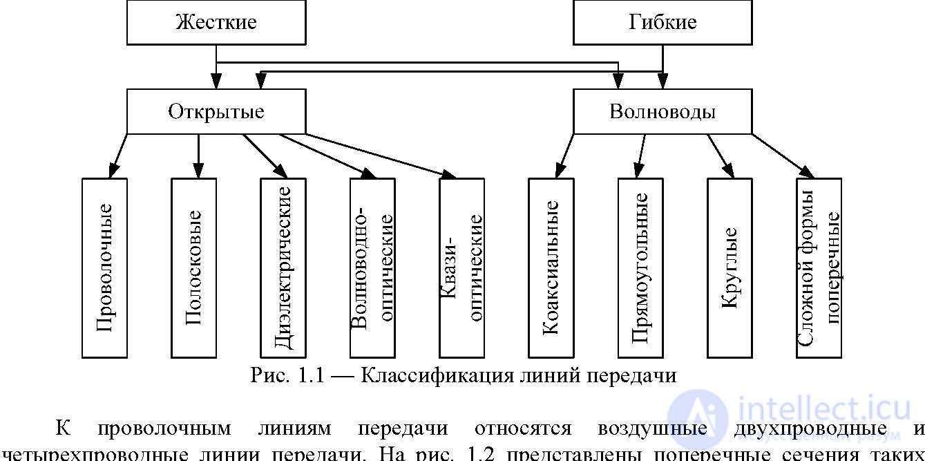
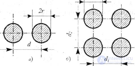
transmission lines. Line conductors may be covered with dielectric. The main type of wave in them is the Τ-wave. In four-wire lines, pairwise connected conductors are excited, for example, vertical, horizontal, or diagonal.
Such transmission lines are used in the ranges of hectometer, decametra and meter waves. Asymmetrical and symmetric striplines, slit and coplanar lines are referred to as stripline transmission lines. The cross sections of such lines and the structure of the fields in them are shown in Fig. 1.3. They are used in the decimeter, centimeter and wavelengths of the millimeter wave. The main wave of asymmetrical and symmetric strip lines is the T-wave. In the slit and coplanar lines, the Η-wave is the main one.
a - two-wire; b-four-wire

a B C D)
Fig. 1.3 - Cross-sections of strip transmission lines: a) asymmetrical; b) symmetrical; c) slotted; d) coplanar
There are also microstrip transmission lines. These include strip lines, in which the dielectric plate (substrate) has a large relative dielectric constant r (more than 10) and small losses. Therefore
the geometrical dimensions of devices made on the basis of such lines are reduced in

times. As a dielectric substrate microstrip lines are used
polycore, sitall, silicon, sapphire, etc. To reduce losses in strip lines, air is used as a dielectric. Such lines are called air or high-Q stripes.
Dielectric transmission lines are classified according to the shape of the cross section. Some of them are presented in fig. 1.4. Such lines are used in the range of millimeter waves. The main type of wave is a hybrid non-wave.
With distance from the dielectric, the amplitude of the wave propagating along the line decreases rapidly. The presence of a metal screen in the mirror dielectric lines (Fig. 1.4, d, e, g) allows you to save the polarization structure of the field of the propagating wave.

Fiber optic transmission lines are used in the dm (submillimeter) and optical ranges. They represent a dielectric line of circular cross section, made of quartz, with several simultaneously propagating wave types. A transmission line in which several types of waves (modes) can simultaneously propagate at a given frequency is called multimode. The diameter of a round fiber is several wavelengths of electromagnetic rings ***. Wave propagation in fiber-optic transmission lines is based on the effect of total internal reflection from the dielectric-air interface. To reduce heat losses in such lines, fibers with a refractive index varying in cross section are used. This leads to a decrease in the geometric path that the beam travels per unit length of the transmission line.
Quasi-optical (ray) transmission lines are irregular lines, the principle of which is based on the use of optical properties of radio waves. In fig.
1.5 schematically presents options for building such lines. They are used in the ranges of millimeter and submillimeter waves.
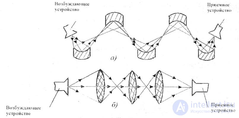
Fig. 1.5 - Beam transmission lines: a) reflective type; b) lens type
Coaxial waveguides are rigid or flexible coaxial cables, the main wave of which is the T-wave. They are used in the ranges from hectometer to centimeter waves, inclusive. Cross-sections of the most common coaxial waveguides in practice are shown in fig. 1.6.
Waveguides of rectangular, circular and more complex cross sections are metal tubes of corresponding cross sections (Fig. 1.7). The main wave in such transmission lines is the lowest Η-wave. Metal waveguides are used in the ranges from the shortwave part of the decimeter to millimeter waves.
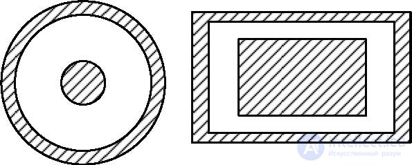
a) b) Fig. 1.6 - Cross-sections of coaxial waveguides: a) round; b) rectangular

Transmission lines can be classified by the order of connectivity of their cross section. The order of connectivity is a geometric characteristic of the cross section of a line and is determined by the number of conductive surfaces. Depending on the number of conductive surfaces, the transmission lines are divided into simply connected, doubly connected, three-connected, multiply connected, and zero connected in the absence of conductive surfaces. For example, metal waveguides are simply connected transmission lines, coaxial waveguides are doubly connected, and dielectric transmission lines (see Fig. 1.4, a, b, c, d) have zero cross-section connectivity.

Comments
To leave a comment
Microwave Devices and Antennas
Terms: Microwave Devices and Antennas