1. The problem of balancing arises when it is necessary to connect devices with symmetrical output terminals to devices with asymmetrical input terminals, or vice versa. Recall that a bipolar input or a multipole output is called symmetrical, the voltages at the terminals of which with respect to the body of zero potential (hereinafter referred to as the screen) are equal in magnitude and inverse in sign. Thus, the problem of balancing relates mainly to devices that use TEM-type electromagnetic waves, since only for these waves the concept of voltage can make sense. In particular, a two-wire line with a TEM type wave is called symmetric if, in each of its sections, the voltage of the wires relative to the screen is equal in magnitude and opposite in sign. In this case, the currents in the wires of the line in each section are also equal in magnitude and oppositely directed.

Fig. 18.6. Asymmetrical power symmetrical vibrator.
The direct connection of symmetrical and asymmetrical devices, as a rule, is unacceptable, because it leads to various disruptions in the operation of the radio link. For example, direct connection to a symmetric half-wave vibrator of a coaxial cable, as shown in Fig. 18.6, leads to an asymmetrical distribution of current and charge on the vibrator, to a change in its input resistance (the vibrator is disturbed), and also to the appearance of a current I f on the outer jacket of the cable, which is the difference of the antiphase currents induced on the cable jacket by the fields from the unequally excited vibrator arms.
The electromagnetic field emitted by the current I f distorts the radiation pattern of the antenna, reducing its directivity factor and efficiency. d . in the transmission mode and reducing the noise immunity of the radio link in the receive mode. These undesirable effects of directly connecting an unbalanced cable with a symmetrical antenna are called the antenna effect of the feeder. Antenna effect occurs in a symmetrical two-wire line when it is directly connected to an asymmetrical device or is asymmetrically located relative to surrounding objects. In this case, the currents in the wires of the line will be different, a differential current arises, which emits intensely.
2. The balancing device is a quadrupole (Fig . 18. 7) with one pair of asymmetrical and one pair of symmetrical terminals. In the following, we will consider balancing devices with unbalanced input and symmetrical output terminals.
The balancing device provides equal and antiphase voltages at the output terminals with respect to the shield (including with respect to the screen of the coaxial cable - its outer sheath). If we now connect a load (antenna, transmission line) having electrical symmetry to the screen to the symmetrical output, then the currents in the screen will not be induced, since symmetrically located elements of these loads will induce equal and opposite currents on the symmetrically located parts of the screen.
3. Symmetrical devices in the form of elements with concentrated reactivity are used where concentrated reactivity (coils, capacitors, transformers, etc.) are physically realizable, i.e. ranges from long waves to decimeters.
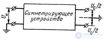
Fig. 18.7. The general scheme of the balancing device.
The simplest balancing device of this type is a balancing transformer, the circuit of which is shown in fig. 18.8, a. The same figure shows the stress diagrams for the turns of the primary and secondary windings. An electrostatic shield is laid between the transformer windings, which is an open loop of foil or a single-layer wrapped, connected at one end to a grounded terminal. This screen eliminates the direct capacitive coupling between the primary and secondary windings, due to which the turns of the secondary winding, symmetrically located relative to its middle, have the same capacitance with respect to the screen.
In fig. 18.8.6 shows a balancing device built on the basis of a single T-link with inductive tuning. From the theory of quadrupoles it is known that if the resonant frequency in  once the working frequency, the voltage at the input and output of the T-link (in the absence of losses in the coil and capacitors) are equal in magnitude and inverse in sign. Thus, terminals A and B are symmetrical with respect to the screen.
If w L >>  then U AB 2U in , and this balancing device transforms the load resistance to the input terminals in the ratio of 1: 4. On a similar principle, multilink baluns also operate, which have an extended bandwidth compared to single barriers.
Single-link and multi-link balancing devices have small losses and therefore are widely used in transmitting devices in the ranges from LW to LCC.
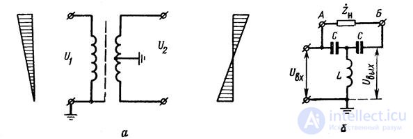
Fig. 18.8. Balun devices on elements with lumped parameters
4. Symmetrical devices consisting of segments of coaxial lines are used in the meter and decimeter wave ranges. The most common constructions of this type and their equivalent circuits are shown in fig. 18.9.
In lines with flexible coaxial cables, the so-called “U-bend” is widely used, as shown in fig. 18.9, a. In this balancing device, the center wire of the power cable is directly connected to one terminal of a symmetrical load; voltage is supplied to the other terminal through a length of coaxial cable L / 2, where L = l / x is the wavelength in the cable.
The voltages at terminals 1 and 2 with respect to the screen are antiphase and equal in amplitude, if we neglect the losses in the half-wave segment of the cable. From the equivalent circuit shown in the figure, it can be seen that the input resistance of the balancing device  , since the half-wave line segment does not transform resistances, and the resistance
  turns on parallel to the input terminals. The 1: 4 impedance transformation turns out to be useful when powering a loop vibrator, which has an input impedance of about 300 ohms, with a 75 ohm coaxial cable.
The U-bend is a narrow-band device, since when the frequency is changed, the bend length becomes different from L / 2 and the antiphase voltage at the output terminals is broken.
In fig. 18.9, b shows a quarter-wave glass balancing device. In this device, the cup and outer sheath of the coaxial cable form a coaxial line closed at the end. If its length is l w = l / 4, then the input resistance  very high, high-frequency currents can not flow on the outer surface of the outer sheath of coaxial cable and it is isolated from the screen. In this case, the currents through the terminals 1 and 2 of the load will be the same. If we neglect the losses, then the input resistance of the short-circuited segment of the coaxial line (loop) is equal to
 .
.
It changes rapidly with frequency, so the “quarter-wave glass” is a narrowband balun. The loop reactivity is sometimes used to compensate for the reactive component of the load resistance.

Fig. 18.9. Balun devices consisting of segments of coaxial lines.
A balancing device that maintains symmetry in a wide frequency band is formed by connecting a short-circuited cable to the central wire of a cable, just like a cable at the cable outer sheath.
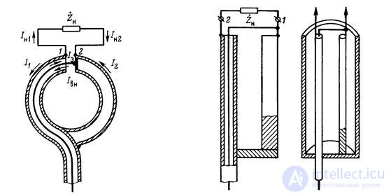
Fig. 18.10. Balancing device 18.11. Baluns
ring rate. ki from two-wire line.
5. Symmetrical attachments allow using sufficiently simple means to provide balancing in the meter and decimeter wave ranges. The principle of operation of these devices is illustrated by the example of a ring balun box shown in Fig. 18.10.
The outer sheath of the coaxial cable and the additional tube of the same diameter with it form a ring, cut so that the lengths of the half-rings formed by the cable and the attachment are exactly equal. In the section of the ring, the central conductor of the cable is connected to the attachment. Symmetric load is connected to points 1 and 2 in the context of the outer part of the ring.
The current flowing from the inner surface of the outer sheath (shield) of the coaxial cable I e at point 1 branches into a current I n1 going to the load, and the current I 1 , the current but the outer surface of the screen, and I e = I n1 + I 1 . The current in the internal core of the coaxial cable I nc at point 2 is the sum of the current I n 2 flowing from the load and the current I 2 from the outer surface of the attachment, i.e. I NR = I H2 + I 2 . As is well known, in any section of coaxial cable, the currents in the central wire and on the inner surface of the screen are: I nf = I e . From here
I Н1 + I 1 = I Н2 + I 2 . 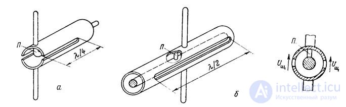
Fig. 18.12. Slot-hole baluns.
The input resistance of the attachment at points 1-2, if we neglect the losses in the metal, is purely reactive and is approximately equal to the input resistance of the twisted two-wire line with a length equal to the length of the half ring. This reactance varies greatly with frequency. If the length of the semiring is approximately equal to l / 4, then the input resistance of the attachment is very large and has little effect on the input resistance of the load.
Practically balancing attachments are made in the form of straight rods (fig. 18.11), which together with the upper part of the cable outer sheath form a short-circuited loop. If the wires of this cable are located symmetrically but with respect to the surrounding objects and the connected load, then its balancing effect will be the same as that of the ring discussed above.
The symmetry of the loop can be broken if its wires are located not symmetrically with respect to the surrounding objects, which is very likely when placing a balancing device, for example, on board the aircraft. To eliminate the influence of surrounding objects, a balancing cable is placed in a shielding metal cup (fig. 18.11), which from the outside can be attached to surrounding metal objects ("grounded").
6. Slot-hole baluns are used in the centimeter and decimeter wavelengths to power the half-wave vibrators using hard coaxial lines. Sketches of these devices are shown in Fig. 18.12.
As is known, the longitudinal slits in the outer sheath of a coaxial cable do not intersect with surface current lines and therefore are not excited. To excite the longitudinal slits in the balancing devices, the outer and inner wires of the coaxial line in the region of the gap are short-circuited with a jumper P. In this case, a coaxial-waveguide type H 11 is excited in the cable . This wave has a longitudinal component of the magnetic field, which creates transverse currents on the inner surface of the outer sheath of the cable, exciting a gap. Wave type H 11 quickly fades away from the jumper, as the cable diameter is chosen less than the critical for this type of wave. If two longitudinal slits are cut symmetrically, then the stresses in the slits will be in-phase and equally directed in space (Figure 18.12, b). In this case, the two halves of the outer sheath of the cable cut by the slits form a two-wire line.
In fig. December 18, a symmetrical device with quarter-wave slits was proved. Its properties are the same as in the balancing device (see. Fig. 18.11).
A balancing device with half-wave slots (Fig. 18.12, b) is obtained from a device with quarter-wave slots. Such a cable segment has a high resistance both in the main wave in the cable and in the wave in the two-wire line and therefore does not violate the excitation symmetry of the vibrator. The device with half-wave slots is more range than with a quarter-wave. It has no radiation from the open end of the coaxial cable, distorting the bottom of the vibrator. This device also has a number of design advantages. The coordination of the power cable with the vibrator is made by selecting the place where the short jumper is turned on.
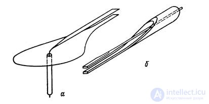
Fig. 18.13. Balun devices based on smooth transitions.
The outer cable sheath of slotted baluns can be "grounded ***" to the left and right of the slots. In order to eliminate the direct radiation of the slits, slotted balancing devices are often placed in a screen, in which two holes are made, through which wires connected to the load are removed.
7. Balun devices built on the basis of smooth transitions have a number of advantages compared to the devices discussed above, especially in the width of the frequency band, in which the balancing effect and coordination with the load are preserved. The principal structural diagrams of these devices are explained in fig. 18.13. In a device with a shielding disk (Fig. 18.13, a), with a disc diameter of one wavelength and more, current flowing into the outer sheath of a coaxial cable is eliminated, since the electromagnetic field excited by the central wire brought out is almost completely intercepted by the disc. A smooth transition from the disk to one of the wires of a two-wire line improves matching and allows you to get a symmetrical excitation of a two-wire line with a slightly smaller disk diameter than in the case of direct connection of the wire to the disk.
In the device shown in fig. 18.13, b, the transition from an asymmetrical TEM wave in a coaxial cable to a symmetrical TEM wave in a two-wire line is made by oblique cut of the outer sheath of a coaxial cable. If the length of the cut is a wavelength and more, then the leakage of currents on the outer surface of the cable is practically not observed.
Balancing devices based on smooth transitions are used in the centimeter and decimeter ranges, where their geometrical dimensions, approximately equal to the wavelength, can be considered acceptable.

Comments
To leave a comment
Microwave Devices and Antennas
Terms: Microwave Devices and Antennas