Lecture
The propagation of electromagnetic waves in gyrotropic media and the properties of ferrites in the microwave range are usually studied in detail in courses on the theory of the electromagnetic field. This reminder paragraph provides basic information from this area that is necessary when studying transmission line nodes that include various ferrite elements.
1. Ferrites are chemical compounds produced from magnetite (ferrous oxide iron oxide FeO * Fe 2 O 3 ) by replacing bivalent iron in it with some other metals. Ferrites are made from powdered mixtures of magnetite and oxides of the corresponding metals.
Ferrite is a low conductivity semiconductor. The dielectric constant of ferrite e r on the microwave varies from 5 to 15, and the magnetic in the absence of bias is close to unity. In the absence of an external constant magnetic field, ferrites at all frequencies of the electromagnetic field acting on them are isotropic materials with mutual properties.
2. Ferrites in a constant magnetic field due to the precession of electrons under the influence of the microwave electromagnetic field change their parameters when the direction of rotation of circularly polarized waves changes and when the direction of propagation of electromagnetic waves changes relative to the direction of the applied constant magnetic field. Due to these properties, feeder elements and nodes with ferrites change their characteristics when the direction of wave propagation changes, that is, they do not obey the principle of reciprocity. Nonreciprocal effects are observed in ferrite both with a longitudinal magnetizing field (the direction of the field coincides with the direction of propagation of electromagnetic waves), and with a transverse biasing field.
3. The Faraday effect is to rotate the plane of polarization of electromagnetic waves as they propagate in ferrite along the lines of force of a constant magnetic field.
Let the electromagnetic field at some point A (Fig. 18.2, a) have vertical polarization and propagate (vector P) along the lines of force of a constant magnetic field. After passing the path of length l, the same field at point B will have an electric vector rotated by an angle  clockwise. If, without changing the magnetic field H o , to direct electromagnetic waves from point B to point A (Fig. 18.2, b), then the electric vector will turn to the same angle but in the course of the wave counterclockwise. It is easy to see that in space the electric vector rotates in the same direction. This is one of the manifestations of irreversibility.
The Faraday effect is explained by the fact that in gyrotropic media the effective magnetic permeabilities for circularly polarized waves have different values for right rotation (m g + ) and left rotation (m g - ) and depend differently on the applied magnetic field. This is illustrated in Figure. 18.2, c, which shows the graphs of the values of m r for relatively weak constant magnetic fields, which are used in devices based on the Faraday effect.
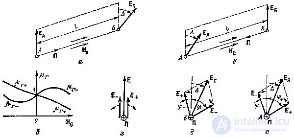
Figure 18.2. To the explanation of the Faraday effect.
The rotation of the polarization plane of a linearly polarized field can be explained on the basis of representing the linear polarization field E as the sum of two circular polarization fields of the right Е + and left rotation Е- (Fig. 18.2, d).
The propagation speeds and wavelengths of fields of different directions of rotation will be different.
 ;
;
 . (18.6)
We now consider the picture of the addition of fields at the same time at points A and B.
Suppose that the direction of propagation coincides with the vector H o (H o > 0 in Fig. 18.2, c). The vectors E + and E- at point B (Fig. 18.2, e) will lag in phase from the corresponding vectors at point A (Fig. 18.2, d) due to the difference in travel by an angle
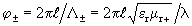 .
.
Since when H o > 0 m r + <m r - , then the vector E + will lag behind at a smaller angle than the vector E -. In this case, the resulting vector will turn to the right along the wave at an angle = 0.5 (j - - j + ).
Now let picture pic. 18.2, g corresponds to point B and the wave propagates towards the field H o , which corresponds to negative values of H o in fig. 18.2, c. Since in this case m r + > m r - , then at point A (fig. 18.2, е) the vector Е + will lag behind at a larger angle than the vector Е - and the resulting vector will turn left to the angle = 0.5 (j + -j - ). It should be borne in mind that in fig. 18.2, the wave goes to the reader, so the rotation of the vectors in the drawing clockwise corresponds to the left rotation. With weak magnetic fields, the angle D is proportional to H o and l. With increasing Н о , the effect of saturation occurs, and the angle D depends mainly on the length of the path traveled by the wave.
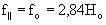
4. Ferromagnetic resonance occurs in ferrites with both longitudinal and transverse magnetizing fields. With longitudinal magnetization, resonance is observed in the case when the frequency of circular polarization waves of right-hand rotation approaches the electron precession frequency (to the frequency of gyromagnetic resonance) f 0 = 2.84N 0 .
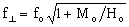
The transverse magnetization gives a large resonant frequency f ^ than the longitudinal (with the same H o ). At a given operating frequency, transverse resonance occurs at lower field strengths. The relations between the resonant frequencies and the corresponding values of the magnetizing constant field are
 ;
;  , (18.7)
where M 0 - the ferrite magnetization; f is expressed in megahertz, and H 0 - in Oersteds.
The relative magnetic permeability of ferrites is a complex value and can be written as
m g + = m ' r - + im " g + ; m r - = m' r - + im" r - .
The terms with two strokes are determined by the loss in the ferrite, and m " r - << m" r + .
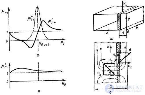
Figure 18.3. The dependence of the magnetic permeability 18.4 To clarify the effect of non-
the catemability of ferrite on the microwave from a constant reversible phase shift of the magnetizing field
The approximate view of the dependence of magnetic permeability on the magnetizing field is shown in Fig. 18.3 for some fixed frequency of propagating cola *** s.
The frequency of the ferromagnetic resonance f 0 by changing the applied field H 0 can be chosen equal to the frequency of the col *** field. In this case, the waves of the right rotation will sharply weaken ***, while the waves of the left rotation will pass without noticeable attenuation. A change in the direction of propagation of circularly polarized waves at a fixed value of H 0 is equivalent to a change in the direction of rotation. Thus, at f = f 0 , right-rotation waves propagating along Н 0 will experience damping, but they will not propagate against H 0 .
5. The irreversible phase shift of circularly polarized waves is observed in longitudinally magnetized ferrites, i.e. with the propagation of waves along the N about . From Fig. 18.2, it follows that for waves of different directions of propagation (different directions of rotation), the magnitudes m ' r , and with them the phase velocities, will be different (in Fig. 18.2, m r = m ' r).
The phenomenon of irreversible phase shift also takes place in thin ferrite plates with transverse bias in a rectangular waveguide with a wave of type H 10 (Figure 18.4, a). The ferrite plate is located between the middle of the waveguide and one of the walls and is magnetized by a weak magnetic field H 0 , perpendicular to the direction of propagation. The structure of the H 10 wave field in the waveguide with a small plate thickness is almost not disturbed.
The magnetic field of the H 10 type, as is known [1], has a rotating polarization at all points, with the exception of the middle plane of the waveguide (x = a / 2). In the coordinate system of fig. 18.4 expressions for the complex amplitudes of the magnetic field are
 ,
,
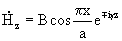 ,
,
where B is a coefficient characterizing amplitude; g is the propagation constant; the upper signs correspond to the distribution in the direction of positive, and the lower - negative z.
This shows that the components of the magnetic field differ in phase by ± p / 2, i.e. The magnetic field has a rotating polarization about an axis perpendicular to the wide walls of the waveguide. Purely circular polarization takes place at such values of x, when H x = H z , i.e. at points of planes separated from the narrow walls of the waveguide at a distance
 .
.
The resulting vector rotates in the direction of the component lagging in phase. When waves propagate in the direction of negative z (Fig. 18.4,6) at the points to the right of the middle of the waveguide (x <a / 2), the component H z lags in phase and the field rotates counterclockwise, i.e. has a left polarization, if you look at the waveguide from top to bottom - in the direction of negative y. At the points to the left of the middle of the waveguide, the field has a polarization of right rotation. If you change the direction of propagation to the opposite direction of rotation also changes to the opposite at all points inside the waveguide.
When the wave propagates in the direction of negative z (Fig. 18.4, b) on the right, where the ferrite plate is located, the field has a polarization of left rotation. Since the vector H 0 is directed towards the axis of rotation of the field, the phase velocity is determined by some effective value of m r - . When propagating in the direction of positive z in the region of the plate, the magnetic field has the polarization of the right rotation and the phase velocity is determined by the effective permeability m r + .
Since m r + and m r - have different values, then the phase shift per unit length of the plate in the forward and reverse directions of propagation will be different, i.e. irreversible.
For ferrite plates of limited length, the concept of a differential (differential) phase shift is introduced, which is equal to the difference in phase shifts when electromagnetic waves travel along the plate in the forward and reverse directions. In this case, a phase shift equal to zero is attributed to one direction of propagation, and the resulting differential phase shift (usually negative, corresponding to a phase lag) is attributed to another.
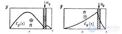
Fig. 18.5. The effect of "displacement" of the field.
With respect to differential phase shift, transferring a plate from the right wall to the left is equivalent to changing the direction of propagation.
A. L. Mikaelyan showed that for very thin ferrite plates the maximum value of the differential phase shift y is obtained when d »a / 4. With increasing plate thickness for maximum y the plate should be moved closer to the side wall. Given the magnetizing field and the characteristics of the ferrite, it is possible to find a plate thickness that provides the maximum y when the plate is located near the wall itself. This is widely used to simplify device design and improve heat dissipation from the plate.
6. The effect of "field displacement" is observed in waveguides with relatively thick ferrite plates when magnetized by a strong transverse field H 0 . The essence of the phenomenon is that with one direction of propagation ferrite has a magnetic permeability, the fields are significantly higher than one, and the electromagnetic field is concentrated near itself, and with the opposite direction of propagation the magnetic permeability of ferrite is close to unity, and ferrite has little effect on the field structure. The difference in magnetic permeability is explained by the considerations outlined in the previous paragraph. Figure 18.5, a shows the distribution of the amplitudes of the electric field in the cross section of the waveguide for propagation in the direction of positive z, and in Fig. 18.5, b - in the direction of negative z.
7. In conclusion, we note that in devices with ferrites, the difference in their properties is observed not only when the direction of propagation changes, but also when the direction of the constant magnetic field H0 is reversed. In their action, these changes are equivalent. Due to this, and the use of switched solenoids to create a magnetizing field H 0, it is possible to build high-speed valve, switching, ramifying, decoupling, polarization and other nodes.

Comments
To leave a comment
Microwave Devices and Antennas
Terms: Microwave Devices and Antennas