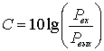
Attenuator is a device designed to attenuate the power coming from the source ***. The main characteristic of the attenuator is the amount of power attenuation introduced by it.
 db (5.1)
where C is the attenuation in decibels;
R I - power input attenuator;
R o - power output attenuator. Attenuators are divided into the following types.
1. Limit, based on the principle of attenuation of the electromagnetic field in waveguides, whose dimensions are less critical. If for a given frequency f or wavelength l the waveguide is in a critical mode, that is, l > lcr (where lcr is the critical wavelength), then the field in such a supercritical waveguide will exponentially decrease. This field attenuation is not due to the absorption, but the reflection of energy. The exponential law increases with decreasing transverse dimensions at a constant wavelength.
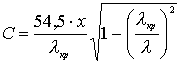
The attenuation value of the limit attenuator is:
 db, (5.2)
here x is the distance between the elements of communication.
Usually attenuators are calculated on a specific type of wave E and H, excited in a circular waveguide. This turns out the most simple design. Waveguide limiting attenuators are rarely used, so they will not be considered further.
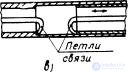
Schematically, the design of coaxial limiting attenuators is shown in fig. 5.1. Attenuators for type E 01 waves have a capacitive coupling (Fig. 5.1, a, b), and attenuators with inductive coupling (Fig. 5.1, c) excite H 11 waves in a circular waveguide .

but)
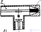
Fig. 5.1. Limit attenuators: a — direct capacitive type; b — angular capacitive type; in - direct inductive type.
For a circular waveguide with a diameter of 2 g, the critical wavelength of type E 01 is equal to:
 , (5.3)
and for the wave H 11 is equal to:
 , (5.4)
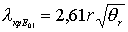
If r << l , then attenuation attenuator for the wave type E 01 can be determined by the formula
 db, (5.5)
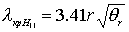
and for wave H 11
 db, (5.6)
This shows that the attenuation is proportional to the distance between the elements of communication. However, this proportionality exists only for large values of x, which will be discussed in more detail in § 5.2.
2. Absorbing attenuators based on the principle of absorbing electromagnetic energy by absorbing materials.
3. Attenuators based on the power division principle. As such attenuators, directional couplers are used, the main types of which are discussed earlier.
When choosing an attenuator type, you should be guided by the following main parameters: working frequency range f min - f max ( l max - l min ), insertion attenuation - C, dB initial attenuation - C min , dB (for variable attenuators), maximum dissipated power - P max , the coefficient of the traveling wave (K bv ), the total error D C.
Usually, absorbing attenuators of the absorbing type are used as measuring and decoupling attenuators, and limiting attenuators are used for accurate measurements and as standards. Achievable measurement accuracy limit attenuators 0.05 dB, absorbing - 0.1 dB.
The initial attenuation of the limiting attenuators cannot be obtained less than 10 dB. With absorbing attenuators with a particular design, the initial attenuation can be obtained almost zero. The maximum attenuation of limiting attenuators of the order of 100-140 dB, absorbing - up to 40 - 60 dB. Structurally, attenuators are made in the form of variable and fixed waveguides, coaxial and strip.
Matched loads are widely used in measurement technology as microwave equivalent devices. Loads are often an integral part of directional couplers and serve to absorb the return wave in the auxiliary line.
The main parameters are the following loads.
Operating frequency range. Waveguide loads typically operate over the entire operating frequency range of the applied waveguide.
The value of K bv in the working frequency range. Good loads of K bv are of the order of 0. 95–0. 97.
The amount of power dissipation. If the load is calculated on the scattering of medium and high power, then in this case the quality of matching is not decisive and the value of K bv of about 0.91 is acceptable .
Structurally, the loads are made in the form of a segment of a short-circuited line, inside which the absorbing element is placed. As loads can be used matched attenuators, the attenuation of which is not less than 25 dB.
Below will be considered the load, designed for small and medium power.

Comments
To leave a comment
Microwave Devices and Antennas
Terms: Microwave Devices and Antennas