Lecture
In modern radio engineering systems, amplitude control devices (multichannel switches, attenuators, amplitude modulators, limiters) and phase (phase shifters) of the microwave signal are widely used.
For these purposes, using microwave diodes. The control microwave diode can be included in the line sequentially or in parallel.
In-microstrip line unpackaged diodes are usually connected in parallel.
The principle of the multi-channel switch (Fig. 4.1) is that when a positive bias is applied, the diode opens, its resistance becomes much less than Z0 and the line in this section is shunted by a diode.

Fig. 4.1 - Multichannel switch circuit
The input power is reflected from this section of the line. If a negative bias is applied to the diode, then it closes, its resistance becomes large and does not shunt the line. A small amount of switching power is absorbed in the diode. This allows switches for relatively high power on low-power devices. If this power is small (less than 1 W), then you can use microwave diodes of various types: varactors, tunnel diodes, etc. If the power level exceeds 1 W, then only p-in — diodes capable of dissipating up to 10 W of average power are suitable. It should be noted that the insertion loss in the switch in the transmission mode LP and the locking LЗ are related by
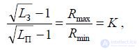
where Rmax, Rmin are the diode resistances when applying negative and positive bias, respectively, K is the quality of the p-in diode.
Typically, switches develop to the maximum level of switching power. In this case, it is advisable to select the switch operation mode so that the same power is absorbed in the “on” and “off” positions in the diode. In this case, about 6% of the switched power is absorbed in the diode. The losses in the “on” mode are 0.5 dB, in the “off” mode (26 ... 28) dB. If you want to increase the insertion loss in the "off" mode, you can install several diodes along the line at a distance of a quarter wavelength. Power control one p-in
- the diode is (0.03 ... 0.1) W.
If you need to reduce the power control (for example, with a large number of diodes), you can apply varatractors TIR. With these devices, when the bias voltage changes, the capacitive conductivity changes. The leakage current in them does not exceed 10 -14 A, because of which the required control power is significantly reduced.
Based on a single channel switch, electrically controlled attenuators are created. In them, the bias voltage of the diode is smoothly changed within ± Ucm. In this case, the attenuation varies within (0.5 ... 28) dB.
If a varactor or a Schottky barrier diode without external bias is switched on, then a constant voltage of about 1 V is maintained on it due to the passing signal, i.e. the amplitude limit of the signal occurs. Such schemes are used in radar to protect the input circuits of the receivers and in the FM receivers to eliminate spurious amplitude modulation.
The switching properties of p-in-diodes are used to create discrete microstrip phase shifters (Fig. 4.2).

Fig. 4.2 - Schemes of a single discharge of microstrip phase shifters with switching segments of lines (a), bridge (b), loop (c)
Such phasers to simplify their control are built on the principle of binary digit capacity.
In practice, switches and attenuators made on broadband directional couplers (SHNO), which are used in the development of modulators, are widely used. In fig. Figure 4.3 shows the antenna switch on two 3 dB bridges.
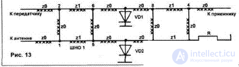
Fig. 4.3 - Antenna Switch Diagram
When transmitting VD1 and VD2 open, power is transmitted to points 5 and 6 and does not flow into the antenna. Reflecting through open diodes, the signals with a phase shift of 90 °, adding up to SHN1, enter the antenna in phase. Due to the imperfection of the elements VD1 and VD2, the power leaks into the shoulders 7 and 8, while it is in-phase folds up in arm 3 and is quenched by resistor R and phase-forward in arm 4 (no signal). When receiving the diodes are closed, the signal from the antenna is divided in half in the shoulders 5 and 6 and transmitted to the shoulders 7 and 8, respectively. In this case, 4 signals are in phase, av 3 is in antiphase (no signal).
If in the arm 2 to install the resistor R = Z0, the circuit will turn into a switch (arm 1 - input, 4 - output). If VD1 and VD2 are open, the “off” state is closed, “on” is closed. If the control current is not applied in jumps, but smoothly, you can smoothly modulate the output power.
Attenuator based on a single SHNO is depicted in Figure 4.4.
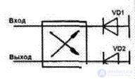
Fig. 4.3 - Attenuator circuit based on a single SHNO
Entry and exit are untied shoulders. As in the previous case, you can smoothly modulate the input signal.
In the microwave technique, devices that use ferrites placed in a constant magnetizing field are used: resonant ferrite valve, ferrite valve at field displacement, ferrite Y-circulator, ferrite circulator based on the Faraday effect, etc.
Ferrite has both magnetic properties of a ferromagnet and electric dielectrics (dielectric constant r 5 ... 20, tangent of angle
4 3 4
loss tg 10 ... 10, specific conductivity 10 ... 10 6 sim / m). In the absence of a constant magnetic field, the initial magnetic permeability is almost equal to
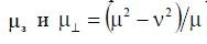
r unit. In ferrites, magnetized by a constant magnetic field, the relative magnetic permeability is a braid *** an symmetric second-rank tensor, that is, described by nine scalar quantities:
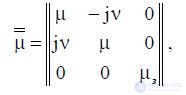
where , and s are scalar values that determine the value of the relative magnetic permeability of ferrite.

The real components of the magnetic permeability tensor determine the phase velocity of propagation of an electromagnetic wave, and the imaginary components determine the magnetic field in
ferrite. The expressions for the components are given in [6].
The reaction of magnetized ferrite on the electromagnetic field of the microwave depends substantially on the ratio between the propagation direction of the electromagnetic wave in the ferrite and the direction of the magnetizing field. With transverse magnetization, the direction of the H vector of the magnetizing field is perpendicular to the direction of wave propagation, and with longitudinal bias, these directions coincide. In both cases, the magnetic permeability of the ferrite can be expressed through the effective scalar relative magnetic permeability:
 - with transverse bias
and 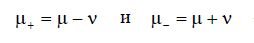 - with longitudinal bias.
In an unbounded ferrite medium with transverse magnetization, the electromagnetic process can be described by two linearly polarized waves:
- ordinary, for which the vector of the intensity of the microwave magnetic field is polarized in the direction coinciding with the direction of the magnetizing field and the effective magnetic permeability of the ferrite is equal to
s
;
-
extraordinary, in which the vector of the intensity of the microwave magnetic field is polarized in a plane perpendicular to the direction of the magnetizing field and
effective magnetic permeability.
These waves have different propagation speeds. A phase shift occurs between them, which leads to a change in the polarization of the electromagnetic field in the propagation path of the wave from linear to circular and vice versa. This phenomenon is called birefringence or the Cotton-Mouton effect. In decoupling devices (valves, Y-circulators) only an extraordinary wave is used.
With longitudinal magnetization, the electromagnetic process in ferrite can be described by two waves with circular polarization in different directions: “+” (right-handed) and “-” (left-handed), for which the ferrite has effective magnetic permeabilities and , respectively. U right-handed
waves the vector of the magnetic field rotates clockwise for an observer looking in the direction of the magnetizing field, and for the left-handed polarized wave it has the opposite direction. The propagation rates of these waves are different, therefore a phase shift occurs between them. The direction of rotation of the polarization plane is determined only by the direction of the magnetizing field and does not depend on the direction of propagation of the electromagnetic wave. This non-reciprocal phenomenon is called the Faraday effect.
In [7] it was shown that the real part of the effective magnetic permeability is determined from the formula 2 '

Thus, an extraordinary wave can be represented by a superposition of two waves with circular polarization of the microwave-magnetic field vector. In this case, the direction of propagation of the wave lies in a plane perpendicular to the direction of the magnetizing field. Most microwave ferrite devices use rectangular waveguides with a wave of type H10. In general, this wave is linearly polarized. However, there are two longitudinal planes parallel to the narrow wall, where the magnetic field has a purely circular polarization. The directions of rotation of the microwave magnetic field vectors in these planes are mutually opposite and reverse in direction when the direction of propagation of microwave energy in the waveguide changes. In arbitrary longitudinal sections of the waveguide, the microwave magnetic field has an elliptical polarization. Thus, when designing waveguide resonant valves, ferrite liners, usually in the form of plates, are placed along the waveguide so that their axial symmetry lies in one of the planes with circular polarization of the microwave magnetic field. In the long wavelength part of the centimeter and in the decimeter wavelength range, waveguide resonance valves with ferrite liners located in the H plane are used. They require a high value of the external magnetic field. This allows you to avoid mutual losses in the field of "weak fields" in the mode when the magnetization of the ferrite does not reach saturation. In the centimeter range of wavelengths, waveguide valves with field displacement are used (Fig. 4.4).

Fig. 4.4 - To clarify the principle of the valve at the displacement field
They contain: a permanent magnet 1, creating a transverse magnetizing field; ferrite liner 2; resistive film 3. If the ferrite insert is magnetized by a transverse constant magnetic field
so that the real part of the effective magnetic permeability ' becomes negative, one of the propagating waves (“reverse”, designated in Fig. 4.4 as E 4.4) acquires the character of a surface wave. Such a wave propagates along the surface of the liner and has a maximum amplitude of the electric field strength at the boundary section of a ferrite — an unfilled waveguide. As the distance from this boundary increases, the field amplitude decreases exponentially. The wave of the opposite direction (“straight”, indicated in Fig. 4.4 as E ) is not superficial, the change in the amplitude of the field strength in the cross section is harmonic and it differs in structure from the basic type of the H 10 wave and
has the form as shown in fig. 4.4.
If a thin resistive film is applied to the right (according to Fig. 4.4) surface of the ferrite insert, the “reverse” wave will be absorbed much more than the “direct” wave, which has a small (close to zero) field amplitude at the location of the absorbing film.
With a change in the strength of a constant magnetic field, the properties of the ferrite plate will change, which affects the characteristics of the valve. In tab. 4.1 shows the values of the main parameters of the valves: direct Lр and reverse Lр
attenuations and the own CWS, as well as for comparison, the values of the intensity of the constant magnetizing field H 0 are indicated.
Tab. 4.1 - Main parameters of ferrite valves
| Valve type | L pr , dB | L arr , dB | U KST | H oh A / m |
|---|---|---|---|---|
| Resonance | 0.1 ... 1.0 | 25 | 1.05 | 198.9103 ... 222.8103 |
| At offset field | 0.5 ... 1.0 | 20 ... 25 | 1.1 ... 1.2 | 23.87103 ... 39.8103 |
| On the Faraday effect | 0.5 ... 1.0 | 20 | 1.25 | 796 ... 1,194103 |
Triplex circulators. In addition to valves, circulators are used in microwave technology (Fig. 4.5), which allow to provide isolation of channels and harmonization of microwave devices. A circulator is an end connection of three or four strip lines or waveguides in the H-plane at an angle of 120 ° or 90 °. In the center of the connection, a ferrite disk is installed, which is in a permanent field of magnet.
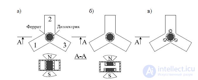
Fig. 4.5 - Designs of three-shoulder Y-circulators
The most simple in design is a circulator in which the ferrite is surrounded by a dielectric sleeve (Fig. 4.5, a). The design of the circulator for the operation of a pulsed power output is different in that it uses two ferrite disks placed on the same axis with a small gap between the disks (Fig. 4.5, b). To ensure matching at the inputs of the circulator in a wide range of frequencies, dielectric pins are used that are placed relative to the ferrite disk as shown in fig. 4.5, c.
The action of the circulator can be explained as follows. The H10 wave entering the shoulder 1 diffracts on a ferrite cylindrical liner and
excites surface waves of equal magnitude enveloping the ferrite in opposite directions. The interaction of these surface waves with magnetized ferrite is characterized by different values of magnetic
permeability. In this case, the phase velocities of surface waves turn out to be different. By selecting the diameter of the ferrite cylinder and the magnitude of the magnetizing field H0, it is possible by adding surface waves to an antinode of the electric field at the center of the shoulder 2, and an electric field node at the center of the shoulder 3. In this case, the energy from the shoulder 1 goes to the shoulder 2 and does not go to the shoulder 3. If energy is supplied from the side of the shoulder 2, then it is transferred to the shoulder 3 and does not flow to the shoulder 1. When energy is supplied to the shoulder 3, it is transmitted to the shoulder 1 and not to the shoulder 2. In actual designs of circulators, the leakage takes place STI from shoulder to shoulder 1 3 it.d. Therefore, to characterize circulators, such parameters as the interchange between the shoulders are applied.
Lр and direct losses Lр. Y-circulators are sensitive to environmental ambient temperature, magnetic field strength, ferrite size, etc. To eliminate this, ferrite is placed in a dielectric bushing, which can be a peculiar element in the setting of the circulator, since the width of the working strip can be adjusted by selecting the size of the meter. For example, the characteristics of some circulators are presented in Table. 4.2.
Tab. 4.2 - Characteristics of some Y-circulators
| The size | Relative | Options | ||||
|---|---|---|---|---|---|---|
| Type of | cross-section of waveguide, mm | operating frequency band,% | ||||
| Lsp, dB | Lпр, dB | UKСТ | maxP, W | |||
| 3ЦВ-103В | 23x5 | 12 | > = 20 | <= 0.5 | <= 1,2 | ten |
| 3KV-108 | 23x10 | 9 | > = 20 | <= 0.5 | <= 1,2 | ten |

Comments
To leave a comment
Microwave Devices and Antennas
Terms: Microwave Devices and Antennas