Lecture
Linear antenna array.
The main modes of radiation.
The radiation field of a linear antenna array.
Analysis of her radiation pattern.
The direction of action of the simplest antenna - a symmetric vibrator - is low. To increase the direction of action, even at the first stages of the development of antenna technology, they began to use a system of vibrators - antenna arrays (AR). At present, antenna arrays are the most common class of antennas, the elements of which can be either weakly directed emitters (metal and slotted vibrators, waveguides, dielectric rods, spirals, etc.), or highly directional antennas (mirror, horn, etc.).
The use of antenna arrays is due to the following reasons. A grid of N elements allows you to increase approximately N times the directivity gain (and therefore the gain) of the antenna compared to a single emitter, and also narrow the beam to increase the accuracy of determining angular
coordinates of the radiation source in navigation, radar and other radio systems. With the help of the grill it is possible to raise the electric
antenna strength and increase the level of radiated (received) power by placing independent channels in the grating channels
high frequency energy amplifiers.
One of the important advantages of the gratings is the ability to quickly (inertialess) view of the space due to the swing of the antenna beam
electrical methods (electrical scanning). The noise immunity of the radio system depends on the level of the side lobes (SLL) of the antenna and
Possibilities of adjustment (adaptation) to its interference environment. Antenna array is a necessary link to create
such a dynamic space-time filter, or simply to reduce UBL. One of the most important tasks of modern avionics is the creation of an integrated system that combines several functions, such as radio navigation, radar, communications, etc.
There is a need to create an antenna array with electric scanning with several beams (multipath, monopulse, etc.), operating at different frequencies (combined) and having different characteristics.
There are a number of structural and technological advantages of antenna arrays for airborne and ground devices.
compared to other classes of antennas. So, for example, by improving the overall dimensions of on-board equipment
occurs through the use of printed antenna arrays. Reducing the cost of large radio astronomy telescopes is achieved through the use of mirror antenna arrays.
Antenna arrays can be classified according to the following main features: the geometry of the emitters in space, the method of their excitation, the patterns of placement of radiating elements in the array itself, the method of processing the signal in the array, the amplitude-phase distribution of currents (fields) over the array and the type of emitters. Depending on the geometry of the arrangement of the emitters, the ARs are divided into linear, arc, ring, flat, convex (cylindrical, conical, spherical, etc.) and spatial (three-dimensional) (Fig. 9.1).
The spatial lattice in the simplest case is a system of two flat lattices parallel to each other in space.
The placement of emitters in the grating itself can be equidistant, for which the step (distance between emitters) is constant (see Fig. 9.1 a, b, c, d, e), and non-equidistant, in which the step changes according to a certain law or random way (see Fig. 9.1, h).
_img_189.jpg)

a) - linear array of emitters; b) - arc lattice;
c) - annular lattice; d) - a flat lattice; d) - a cylindrical lattice;
e) - conical lattice; g) - spherical lattice; h) - non-equidistant lattice
Fig. 9.1 - Antenna arrays
Consider general methods for calculating the characteristics of the AR; it is more convenient at the beginning to consider in more detail the calculation of ARs formed by a system of half-wave vibrators. In a strict electrodynamic formulation, the problem of emitting a system of thin half-wave vibrators is similar to the previously considered problem of emitting a single vibrator. The difference consists in replacing one vibrator with a system of vibrators, each of which is excited by its own third-party source. Acting as in the strict solution of the radiation problem of a symmetric vibrator, it is possible to establish connections between third-party sources and AR parameters. Currents in AR emitters can be found from a joint solution of a system of integral equations.
Such a solution is an order of magnitude more complicated than for a single emitter, and it is very difficult to identify the main laws of antenna arrays. For this purpose, approximate methods are used in the theory of antennas, in which the general problem of calculating AR is conventionally divided into two tasks:
external and internal. The solution to the external problem consists in finding the directivity characteristics of the antenna with a known amplitude-phase distribution of currents (fields) over the elements of the AR. This distribution is considered known from the solution of the internal problem and is achieved by the corresponding selection of external sources of excitation. The solution to the internal problem consists in determining the amplitude-phase distribution in the AR of the assigned third-party sources, which is necessary for the excitation (power) of the AR.
The solution of the external problem can be carried out in a general form for various ARs and then set the directivity characteristics. Therefore, below we dwell in detail on the general approximate method for calculating an external problem. It should be noted that the methods for solving the internal problem turn out to be different for different types of AR emitters and will be considered later. The radiation field of the antenna array is the result of interference of the fields of individual emitters. Therefore, it is necessary to find separately the field from each emitter at a given point in space, and then the sum of the fields of all emitters, taking into account the amplitude and phase relationships, as well as the polarization of the fields.
It is advisable to calculate the radiation pattern of such antennas in the following order:
H. Calculate the amplitudes and phases of the fields created by equivalent emitters at an arbitrary point in space (each separately). In this case, consider the field at a large (compared to the antenna size and wavelength) distance from the observation point to all emitters (the same and equal distance to any emitter). Phase calculation should, however, be carried out taking into account the difference in distances to each emitter. When determining the difference in distances, in order to simplify, we should consider the directions to the observation point parallel for all emitters. When calculating the phases, it is necessary to determine the phases with respect to the phase of the field of any one emitter, taken as the initial one.
4. Determine the amplitude and phase field of the entire antenna by summing the fields of all its emitters, taking into account the amplitude and phase relationships, as well as the polarization of the fields.
When calculating the radiation field of a common-mode antenna with a uniform amplitude distribution, one has to deal with the addition of a number of equally polarized harmonic oscillations with equal amplitudes and phases that differ from each other by the same angle. The sum of such oscillations is defined as the sum (series of such oscillations) of the geometric progression members or in a geometric way.
Let there be: 
We represent each term with a vector having a modulus equal to the amplitude of the radiation field A, and located accordingly to the phase of the oscillation  . When summing the vectors, a regular polygon is formed (Fig. 9.2).
_img_190.jpg)

We describe around it a circle of radius centered at the point O. Then 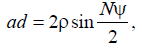
since 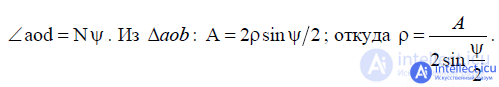 .
.
Thus, the amplitude of the resulting oscillation:
The phase of the resulting oscillation with respect to the phase of the initial oscillation is determined by the angle dab and is equal to
 .
.
The sum of all fluctuations:

where  is the phase difference between adjacent vibrations. The phase of the resulting oscillation is ahead of the phase of the original by an angle
  .
.
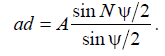
Antenna arrays composed of vertical or horizontal half-wave vibrators have gained distribution (Fig. 9.3, a, b).
Such antennas consist of in-phase half-wave vibrators, equally oriented and located at the same distance d from each other. The direction of the arrangement forms a straight line.
_img_194.jpg)
a - lattice of vertical vibrators; b - lattice of horizontal vibrators; c - to the calculation of linear arterial pathways
Fig. 9.3 - Linear array of emitters
To calculate the radiation patterns, we replace each vibrator with an equivalent point emitter, placing it in the phase center, i.e. in the middle of the vibrator. Then, regardless of whether the horizontal or vertical vibrators are in the grating, the circuit will take the form shown in Fig. 9.3, c. The field of such an antenna is the result of interference of the vibrator fields. We assume that all emitters in the array have the same pattern. Since the vibrators are parallel, the fields are equally polarized, and, therefore, you can use the above formula for the total field. Looking far away
from the antenna, i.e. not distance  , we can assume that
  (see. Fig. 9.3, c).
2 3 n
Let the instantaneous current value in the antinodes of each vibrator be described by the equation 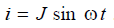
. Then the total field at the observation point from the entire antenna will be:
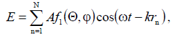
 - the radiation pattern of the equivalent emitter in the grating, which we take in the framework of an approximate theory, the same for all emitters;
A-constant (amplitude) factor, independent of angles 
rn-distance from the n-th emitter of the observation point.
We take the phase of the field from the most distant emitter (in the considered case of the 1st) as the initial one. Then, to determine the phase phase of the field of the nth emitter, it is necessary to first express the distance from this emitter of the observation point through the distance r1.
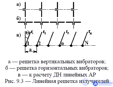
From fig. 9.3, it is seen that
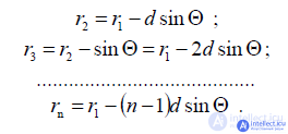
Substituting the value of rn in the formula (9.2) for the field strength, we obtain:
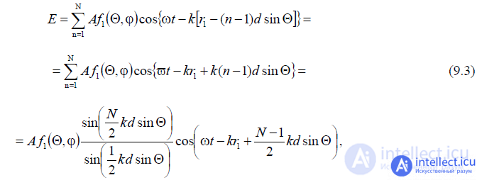
wherein 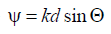 - the phase difference between polyamisosednih emitters
  .
.
Let us analyze the resulting expression. The amplitude radiation pattern according to the formula (9.3) is defined as
is a product of the diagram of the component emitter  by the antenna multiplier
From formula (9.3) it follows that the phase of the field changes with a change in the angle  . Thus, when calculating the distance from the most distant emitter, the in-phase antenna does not have a uniform phase diagram, and the selected distance reference point is not phase
center. In what follows, we will call the phase diagram that part of the expression that determines the phase of the field,
which does not depend on time (9.3)

We will find out whether the antenna in question has a phase center and where it is located.
Suppose that a phase center exists and is located on the line of emitters at a distance x from the 1st emitter.
We denote the distance from the phase center of the observation point by r0 and express the distance r1 by
 Then:
Then:
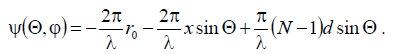
If x0 is the coordinate of the phase center, then this expression at x = x0 should not depend on 
Requiring the fulfillment of this condition, we obtain 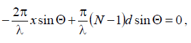
Thus, the antenna in question has a phase center that coincides with its geometric center.
This conclusion is valid in the general case for any common-mode antenna.
When counting the distance from the phase center, taking into account that the field amplitude is practically
does not change when changing the origin within the antenna, the field
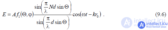
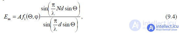
Since the vibrators forming the lattice have a weak directivity, DN
lattice is mainly determined by the lattice factor  . The grating factor depends on the number of emitters and the distance between them, expressed in wavelengths
  (9.5).
This factor does not depend on the angle  , which means that in the plane perpendicular to the emitter line (at
  ),
),
The bottom of the grating coincides with the diagram of a single emitter; the apole increases in proportion to the number of emitters:
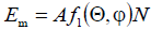 . This follows from the expression (9.4) at
  . In the plane passing through the emitter line (
  ), the grating pattern is different from that of a single emitter. Let in this plane the radiation path of a single emitter be non-directional. Then the lattice DN will be determined only by the lattice factor, which is written in the normalized form as
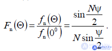
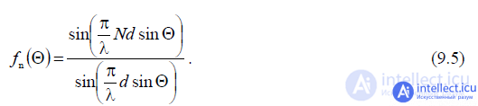
The lattice factor  is a periodic function with a period passing through its maximum and minimum values
  when the angle changes
  . Therefore, the array bottom has a multi-leaf nature (Fig. 12.7., Where the bottom plate of the real antenna is shaded).
_img_197.jpg)
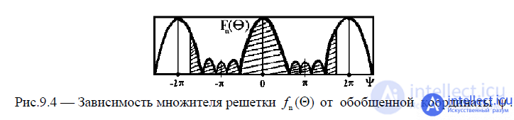
Fig. 9.4 - Dependence of the lattice factor on the generalized coordinate.
In each of the periods of this function, there is one main lobe and several lateral ones. The graph of the function is  symmetrical with respect to points
 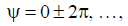 , and the function itself is
  maximum at these values . Between the adjacent main and petals, there are N -1 directions of zero radiation and N -2 side lobes, the maxima of which decrease with distance from each main lobe.
In this case, the smallest petals are those that are in the middle of the interval between adjacent main maxima.
The relative size of the side lobes
 where p = 1, 2, 3, ....
In gratings with a large number of emitters, the level of the first side lobes can be found by a simplified formula:

and when the  magnitude of the first side lobe is 0.217 (or –13.2 dB) relative to the main one.
In practice, it is usually required to obtain MD gratings with one main radiation maximum. For this, it is necessary that only one main maximum of the function fall into the interval of variation of the generalized coordinate  , determined by the inequality
 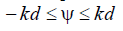 and corresponding to the real LF of the lattice (see Fig. 9.4).

_img_201.jpg)
This will be the case if the width of the change interval  equal to 2kd is less
  . Thus, the distance between adjacent emitters in the grating should be less than the wavelength of the generator. Corner borders of the main lobe
by the level of radiation can be found from formula (9.6) by equating to zero the numerator of the lattice factor 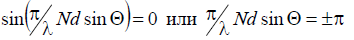 since the factor
the lattice with a change in angle changes much faster than the first factor of formula (9.6), and determines mainly the lattice DN.
From the last relation follows  . With a large number of emitters (N> 4) it is possible to accept
  .
.
Hence the angular width of the main lobe of the NAM  .
.
Thus, to obtain narrow beams, it is necessary to increase the length of the antenna Nd.
But since the distance between the emitters should be less than the wavelength of the generator (to obtain one main maximum radiation), directionality is achieved by increasing the number of emitters of the grating N. The width of the DN at the level of 0.7 field can be determined by the approximate formula:

Formula (9.7) the more accurate, the greater the number of vibrators in the lattice at a given ratio 
In practice, it can be used if  .
.
If the emitters forming a linear in-phase antenna have directional properties in the plane passing through the line of their location (Fig. 9.5), then the distance between the emitters can be taken longer than the generator wavelength (  ).
).
In this case, in the interval of variation of the generalized coordinate  corresponding to the real lattice pattern, there may be several function maxima
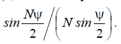
_img_206.jpg)

In the resulting MD, they will be absent if in these directions the MD of a single lattice element has a value of zero or almost zero.
Thus, by choosing the appropriate distance between the emitters (at  ), we can obtain
the resulting radiation with a relatively low level of side lobes.
If the distance between the emitters is chosen so that the influence of their fields on each other can be neglected, then the gain of the grating
calculate by the approximate formula  - the coefficient of directional action of a single emitter in free space
. The considered linear gratings have a directivity in only one plane: in the plane of the emitters

Comments
To leave a comment
Microwave Devices and Antennas
Terms: Microwave Devices and Antennas