Lecture
1. Typical decoupling devices are:
These devices can be made in coaxial, strip-wave versions.
The bridges considered in § 18.8 can also be used as decoupling devices.
Specific electrical characteristics of decoupling devices are: transient attenuation (attenuation) L C and directionality L n . These values are the corresponding power transfer factors (see § 18.1, p. 3). Denote by number 1 the shoulder from which the electromagnetic collars enter the node, 2 and 3 are the shoulders to which the electromagnetic collars are passed with the required attenuation, and 4 the shoulder into which the collars should not do shoulder untied from the input shoulder 1.
For double-shoulder reciprocal nodes, only attenuation is determined; it is equal to L s = -10lg (P 12 / P 1 ). In the four-shoulder nodes, the values of L- 12 = -10lg (P 12 / P 1 ) and L = 13 = -10lg (P 13 / P 1 ) are attenuation for the respective transmission directions, and the values of L n 24 = -10lg (P 14 / P 12 ) and L n 34 = -10lg (R 14 / R 13 ) determine the direction of transmission to channels 2 and 3, respectively, with respect to channel 4.
2. Attenuators are dual-arm devices designed for a given fixed or adjustable attenuation of the intensity of electromagnetic rings ***.
3. Attenuators of the absorption type work on the principle of absorption and scattering for heat of a part of the power of a transmitted electromagnetic wave.
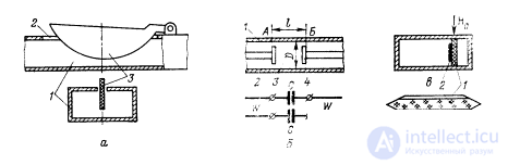
Fig. 18.48. Attenuators.
In fig. 18.48, and depicts an embodiment of a waveguide adjustable attenuator. In a rectangular waveguide 1 with a type H 10 wave, a narrow longitudinal slit 2 is cut in the middle of the wide wall, through which an absorbing plate 3 is pushed into the waveguide. It is a dielectric plate covered with a layer of soot, graphite or another material intensively absorbing electromagnetic waves. The degree of absorption, i.e. the amount of attenuation depends on the area of the plate inside the waveguide.
On the same principle can be built and fixed attenuators.
The reflections in attenuation attenuators are small, and the attenuation is weakly dependent on frequency.
4. Attenuators of the limiting type are based on the use of transmission lines whose transverse dimensions are less critical for a propagating wave type.
In fig. 18.48, b shows the limiting coaxial attenuator. It is formed by a coaxial line 1, the central wire 2 of which has a gap in section 3 with a length l. This section of the coaxial line is a circular waveguide in which an E 01 waveguide wave is excited with the help of disk 4. The diameter D of the waveguide is chosen so that the critical wavelength l cr01 = 1.305D is less than the working wavelength. Waveguide 3 and discs 4 constitute the limiting attenuator itself. Its attenuation increases rapidly with decreasing relative diameter D / l. The length of the limit attenuator is small. So, to obtain attenuation L З = 30 dB (reduction of the transmitted power 1000 times) at the wave l = 10 cm with D = 1.5 cm, the required length of the attenuator is only 1 cm.
The attenuation of limit attenuators strongly depends on the frequency. In an equivalent circuit, an attenuator is represented by a capacitance C (Fig. 18.48, b), the magnitude of which is smaller, the larger L s . At the input of the attenuator, there is a strong reflection of electromagnetic waves, the more, the more L s . Therefore, such attenuators are narrowband.
5. Attenuators using nonreciprocal properties of ferrites are distinguished by the fact that their attenuation depends on the direction of propagation, i.e. for these devices L s 12> L s 21 .
This property defines the valve action of non-reciprocal devices with two inputs. Valve properties are characterized by directivity L n . The directivity (in decibels) can be calculated through the known transient attenuation to the formula
L n = L C 21 -L C 12 .
In fig. 18.48, the cross-section of the valve is shown, based on the effect of field displacement in a rectangular waveguide. The valve contains a transversely magnetized ferrite plate 1, on which an absorbing layer 2 is applied. A sketch of this plate is shown in fig. 18.48,
If on fig. 18.48, in the direction of wave travel corresponds to the direction from the reader for the drawing, then, referring to fig. 18.5, and it can be seen that the absorbing plate is outside the region of an intense electric field. The absorption will be small. When the waves propagate in the opposite direction, the absorber will be at the maximum of the distribution of the electric field, which will cause intense absorption.
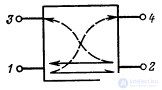
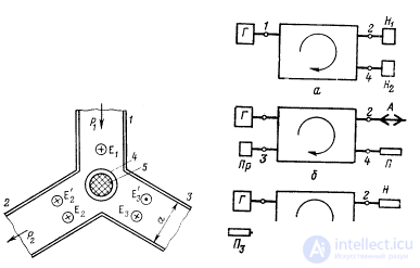
Fig. 18.49. Schematic diagram of the directional coupler.
6. Directional couplers are designed for the directional transfer of electromagnetic energy from one transmission line to another, so that the direction of transmission of energy in the second line depends on the direction of transmission in the first line. If a significant part of the power is transferred from one line to another, then directional couplers can be classified as a power divider, and if a small part, then - to a class of decoupling devices.
Directed couplers can be both reciprocal and non-reciprocal.
In fig. 18.49 shows a schematic diagram of the inclusion, directional coupler, connecting lines 1-2 and 3-4. If electromagnetic energy is transferred from arm 1 to arm 2, then part of it branches off into arm 4, and energy does not flow into arm 3. If the transmission goes from shoulder 2 to shoulder 1, then part of it branches off to shoulder 3, and energy does not flow to shoulder 4.
Let the main gear go in the direction from arm 1 to arm 2. Then the value of L C 12 is called the attenuation in the forward direction, the value of L C 14 is weakened in the direction of the branch, and the value L n = -10lg (P 13 / P 14 ) is directed directional coupler.
7. The main types of directional couplers:
- coaxial and waveguide with single coupling elements having their own directionality (holes and coupling loops);
- coaxial and strip two- and multi-loop;
- strip using scattering fields;
- waveguide multi-hole and multi-rod;
- waveguide with a slot connection.
The designs and operating principles of directional couplers and bridges have a lot in common. For example, a directional coupler, in which the attenuation is 3 dB (the power of the arm 1 is equally divided between the shoulders 2 and 4), is a bridge. This mode, however, is not typical for directional couplers. Created a large number of different on the principle of action and characteristics of directional couplers [1, 3-5]. Consider one of the most common.
8. The waveguide multihole directional coupler (Fig. 18.50) consists of a main waveguide with shoulders 1 and 2 and an auxiliary waveguide with shoulders 3 and 4. The waveguides in a certain area are connected along a wide or narrow wall. Holes 5 are cut in the common wall, the weakening and directionality depend on the number, diameter and location of which.
For an auxiliary waveguide, the coupling holes are emitters forming a linear grating. If the main waveguide in the hole area has a constant width, and the holes are located at the same distance from each other, then this grating will be linear-phase. The phase difference between the excitation of the holes is y = 2pd / L. Electromagnetic waves in the auxiliary waveguide, excited by the holes, propagate left and right through the waveguide. In this case, the phase difference due to the difference in the course of the fields from neighboring emitters at an equal width of the waveguides is 2pd / L. Thus, the phase difference of the excitation of the emitters is equal to the phase difference due to the path difference of the electromagnetic waves between them. As shown in Ch. 3, such a grating is a longitudinal radiation grating with a radiation maximum oriented in the direction of emitters that are out of phase. With the indicated in fig. 18.50 in the direction of propagation the branch of power will occur mainly in arm 4 and to a lesser extent in arm 3. The greater the number of openings, the greater the directivity.
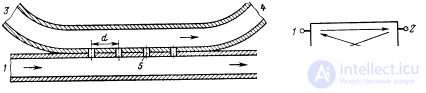
| Fig. 18.50. Multiwave waveguide directional coupler. | Fig. 18.51. Schematic diagram of the four-arm circulator. |
The distance d can be any, however, the best results in matching and directivity are obtained when d = L 0/4 where L 0 is the wavelength in the waveguide at the average frequency of the operating range.
If the power tap is only necessary when transmitting in the direction 1-2, then a load is put in the arm 3 that absorbs the branched power when transmitting in the opposite direction.
9. Circulators are decoupling multichannel devices in which electromagnetic waves propagate from one channel to another only in a certain sequence.
The schematic diagram of the four-arm circulator is shown in Fig. 18.51. The arrows in the figure show the direction of transmission. If the electromagnetic energy is fed into the shoulder 1, then it will pass into the shoulder 2 and will not pass into the other shoulders. When the generator is connected to arm 2, electromagnetic energy will pass only into arm 3, etc. In the example under consideration, the circulation occurs in the sequence
1 ® 2 ® 3 ® 4 ® 1. (18.19)
There may be, of course, other sequences.
10. A phase circulator with two waveguide-slit bridges consists (fig. 18.52) of two successively located waveguide-slit bridges I and II, a dielectric plate D and ferrite plates F with a transverse magnetizing field creating a differential phase shift. The properties of the wave-gap bridge are described in § 18.8 p. 2, and the section of the differential phase shift in § 18.8, p. 7.
Consider the work of the circulator shown in Fig. 18.52, a. The parameters of the ferrite plates and the constant transverse magnetizing field are chosen so that in the upper waveguide, when transmitting from left to right, a phase shift of -p / 2 (phase lag) is created, and when transmitted from right to left, a phase shift that is considered to be zero. In the lower waveguide, the ferrite plate provides the phase shift -p / 2 during the transmission from right to left and zero - with the opposite direction of transmission. These phase shifts in two ferrite plates, located on both sides of the separation wall, are obtained by magnetizing both plates by a transverse field of the same direction. This is convenient as one magnet is required.
In the upper waveguide, a dielectric plate D is installed, which creates a reversible phase shift -p / 2 with respect to the wave in the waveguide without this plate.
We now consider the phase relations in the circulator. In this case, we will take into account only difference phase shifts.
Let the generator is connected to the shoulder 1, and matched loads are connected to the rest of the shoulders. Waves from arm 1 fall into a waveguide-slit bridge I and are divided by it into two streams of equal amplitude that go in the direction of shoulders 2 and 4. After the bridge I, the bridge in the upper waveguide is lagging behind in phase by p / 2 * ** in the lower waveguide, the phase of which will be taken as zero. After passing through the sections of the waveguides with ferrite and dielectric plates of a collar ***, at the input of bridge II in the upper waveguide, there will be a delay in phase at Зp / 2, and in the lower waveguide - delay, which is assumed to be zero. Bridge II, each half of the power is divided in half. Electromagnetic waves, passing from the lower waveguide to the upper and from the upper to the lower, receive a delay in the p / 2 phase. If we now sum up all the relative phase shifts, then it turns out that the stakes of the *** that came along two paths in arm 4 differed to the phase by p, and those that came in arm 2 had the same phase. Since the amplitudes of the waves that came in different ways are the same, in arm 4, the waves are completely mutually compensated, and in arm 2 they are folded, forming a wave of the same intensity as in arm 1. Thus, the electromagnetic anergy from arm 1 passes only into arm 2 .

Fig. 18.52. Phase ferrite circular waveguide bridges
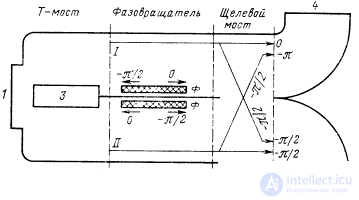
Fig. 18.53. Phase ferrite circulator with waveguide-slot and double T-bridge.
In a similar way, it can be shown that from the shoulder 2 the wheels of the *** fall into the shoulder 3, from the shoulder 4 - into shoulder 1. Consequently, the sequence (18.19) is realized in the considered circulator.
If the direction of the magnetizing field is reversed, then the ferrite plates will create phase shifts indicated in fig. 18.52, b. It is easy to verify that in such a circulator the sequence of channel connections is realized.
1 ® 4 ® 3 ® 2 ® 1. (18.20)
11. The phase circulator with a double T-bridge (fig. 18.53) consists of successively located double T-bridge (see § 18.8, p. 1), whose straight arms are bent at an angle of 90 ° and connected along a narrow wall, a phase shifter with ferrite plates and waveguide-slot bridge.
The shoulder 1 of the circulator is the H-shoulder of the T-bridge, and the shoulder 3 is the E-shoulder of the T-bridge. When waves enter shoulder 1, they will equally come to sections I and II and will not fall into shoulder 3. When waves enter shoulder 3 they will not fall into shoulder 1, but in equal parts and in antiphase will come to sections I and Ii. The constant magnetic field and the parameters of ferrite plates are selected so that the differential phase shifts shown in the figure are formed.
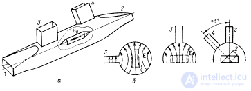
Fig. 18.54. Polarizing ferrite circulator.
The paths of the passage of electromagnetic waves after the T-bridge are shown by arrows, and there is also an additional phase shift of -p / 2 during the passage of the slot-hole bridge. If we add up all the phase shifts and take into account the phase properties of the T-bridge, then it turns out that from shoulder 1 waves pass only into shoulder 2 (for this case, the figure shows total phase shifts), from shoulder 2 - into shoulder 3, etc. Thus, in this case, the sequence (18.19) is realized. When the direction of the magnetic field changes, the differential phase shifts in the phase shifter will change. This change will translate the sequence (18.19) into the sequence (18.20).
On the basis of circulators with ferrites, various waveguide circuits can be constructed, whose properties can be controlled by changing the magnetizing field.
12. The polarization circulator (fig. 18.54, a) is based on the use of the Faraday effect in longitudinally magnetized ferrite. The solenoid creating a constant magnetic field H 0 is not shown in the figure. The circulator in question is four-shouldered, non-reciprocal. Shoulders 1 and 2 are rectangular waveguides, which are connected by a smooth transition to a circular waveguide at the end. The shoulders 3 and 4 are rectangular waveguides, which form a T-shaped parallel connection with a circular waveguide. These shoulders are called lateral.
The dimensions of the circular waveguide are chosen so that only the H 11 wave can propagate in it, and only the H 10 wave can propagate in a rectangular waveguide.
If the polarization of the field of the H 11 type wave is as shown in Fig. 18.54, b, then they say that the side waveguide 3 is in the transmission position, and the end waveguide 1 - in the locking position relative to the H 11 wave. With the polarization of the field of the wave type H 11 shown in Fig. 18.54, in, in the transmittance position, the end waveguide 1 is located, and in the locking position, side waveguide 3. In the locking position, the round and rectangular waveguides are decoupled, and in the transmittance position, the electromagnetic energy completely changes from a rectangular waveguide to a round one, and vice versa. The mashing and transmitting positions for waveguides 2 and 4 are determined in the same way as for waveguides 1 and 3.
The planes of the wide walls of waveguides 1 and 2 are rotated around an axis of a circular waveguide by 45 ° relative to each other. Waveguides 3 and 4 are also rotated at an angle of 45 ° (Fig. 18.54, d).
A ferrite rod is installed along the axis of the circular waveguide. The magnetizing field is directed longitudinally with respect to the rod (along the axis of the waveguide). With the indicated in fig. 18.54, and the H 0 direction, the polarization plane of the H 11 wave rotates counterclockwise when transmitting from shoulder 1 to shoulder 2 and clockwise when transmitting from shoulder 2 to shoulder 1. The parameters of the ferrite rod and the magnitude of the magnetizing field are chosen so that rod, the polarization plane of the H 11 wave rotates at an angle of 45 °.
Consider the transfer of electromagnetic energy through a circulator when connecting a generator to arm 1 and matched loads to the rest of the arms. The shoulder 3 will be in the locking position. After passing the ferrite, the wave type H 11 will turn counterclockwise by 45 ° and will have a polarization in which arm 4 is in the locking position, and arm 2 is in transmission. In this case, the waves pass into the shoulder 2 and do not pass into the shoulder 4. Thus, from the shoulder 1 the electromagnetic energy passes only into the shoulder 2.
Connect the generator to the shoulder 2. The shoulder 4 is locked. After passing the ferrite, the H 11 wave rotates 45 ° clockwise and turns to the transmission position with respect to the shoulder 5, and locking to the shoulder 1. Согласование круглого волновода с плечом 3 осуществляется подбором расстояния между волноводом 3 и эффективной плоскостью отражения от плеча 1 в положении его запирания. Таким образом, электромагнитная энергия из плеча 2 переходит только в плечо 3.
| Fig. 18.55. Ферритовый Y-циркулятор. | Fig. 18.56. Примеры использования циркуляторов. |
Рассуждая аналогичным образом, можно показать, что из плеча 3 электромагнитная энергия передается только в плечо 4, а. из плеча 4 - в плечо 1.
Итак, если вектор постоянного магнитного поля направлен к плечу 1, то циркулятор реализует последовательность (18.19). При изменении направления подмагничивающего поля на обратное циркулятор реализует последовательность (18.20).
13. Ферритовый Y-циркулятор (рис. 18.55) представляет собой три прямоугольных волновода, 1, 2, 3, в которых распространяется волна типа H 11 , соединенных между собой под углом 120° в Н-плоскости. В центре сочленения волноводов размещается ферритовый стержень или диск 5, намагниченный вдоль оси перпендикулярно широким стенкам волноводов. Высота стержня равна высоте волноводов или меньше ее. Стержень обычно помещается в диэлектрический цилиндр 4, который заметно улучшает работу циркулятора и упрощает его настройку, расширяя полосу пропускания.
Если в тройнике нет феррита, то волна, поступающая в плечо 1, делится поровну между плечами 2 и 3. При наличии намагниченного феррита волны, проходящие в плечи 2 и 3, будут суперпозицией двух полей: первичного, обозначенного E 2 и Е 3 , и вторичного, переизлученного ферритовым стержнем (E' 2 , Е' 3 ). Первичные поля в плечах 2 и 3 в силу симметрии будут синфазны и равны по амплитуде. Амплитуды и фазы вторичных полей в плечах 2 и 3 зависят от размеров и электрических параметров ферритового стержня и диэлектрического цилиндра. Параметры феррита можно регулировать подмагничивающим полем. Регулировками можно добиться, чтобы поля Е 2 и Е' 2 в плече 2 были синфазны, а Е 3 и E' 3 в плече 3 противофазны, а их амплитуды одинаковы. При этих условиях электромагнитная энергия из плеча 1 полностью переходит в плечо 2. Так как система симметричная, то коле***ния из плеча 2 будут передаваться только в плечо 3, а из плеча 3 - в плечо 1, т.е. будет реализована последовательность передачи 1-2-3-1. При изменении направления внешнего магнитного поля последовательность передачи также изменится на обратную: 1-3-2-1.
Y-циркуляторы могут быть выполнены также на коаксиальных на полосковых линиях.
Рассмотрим несколько применений циркуляторов в фидерных трактах.
14. Быстродействующий коммутатор на два направления (рис. 18.56,а). Из четырех плеч циркулятора в нем задействовано три. К плечу 1 подключают источник электромагнитных волн Г, а к плечам 2 и 4 - нагрузки H 1 и Н 2 (скажем, две антенны). При одном направлении подмагничивающего поля электромагнитная энергия в соответствии с последовательностью (18.19) проходит в нагрузку H 1 . Поменяв направление тока в соленоиде, создающем подмагничивающее поле, перейдем к последовательности (18.20). При этом электромагнитная энергия пойдет в нагрузку Н 2 . Так как в фазовых циркуляторах подмагничивающее поле имеет небольшую величину, то частота переключении может достигать 10 МГц.
15. Антенный переключатель радиолокационных станций схематически изображен на рис. 18.56,б. В нем применен циркулятор фазового типа с постоянным магнитом. Направление магнитного поля подобрано так, что реализуется последовательность (18.19).
В режиме передачи электромагнитные волны поступают из плеча 1 в антенну А, подключенную к плечу 2. В режиме приема сигналов, отраженных от цели, эетромагнитные коле***ния поступают в приемник Пр, подключенный к плечу 3, и не поступают к передатчику. К плечу 4 подключается поглощающая нагрузка П, в которой поглощаются коле***ния, неизбежно просачивающиеся в это плечо из-за неполной развязки между плечами циркулятора. Из-за неполной развязки часть мощности от генератора поступает и на вход приемника. Для защиты его входных цепей от повреждения на входе приемника ставится защитное устройство в виде разрядника или управляемого вентиля.
16. Вентильное устройство (рис. 18.56,в) служит для развязки генератора и нагрузки. При реализации в циркуляторе последовательности (18.19) электромагнитные волны поступают от генератора в нагрузку Н. Если нагрузка не согласована, то появляются отраженные волны, которые поступают через плечо 2 в плечо 3, где поглощаются в поглотителе П 3 . Поглотитель П 4 устраняет отражение волн, просочившихся в плечо 4. Таким образом, отраженные волны не поступают на выход генератора и условия его работы не зависят от степени согласования нагрузки с линией передачи, подключаемой к плечу 2.

Comments
To leave a comment
Microwave Devices and Antennas
Terms: Microwave Devices and Antennas