Lecture
Plan
Radio waves are divided into frequency ranges: long waves, medium waves, short waves, and ultrashort waves.
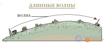
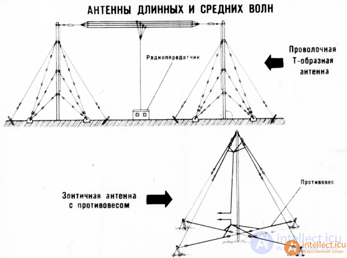
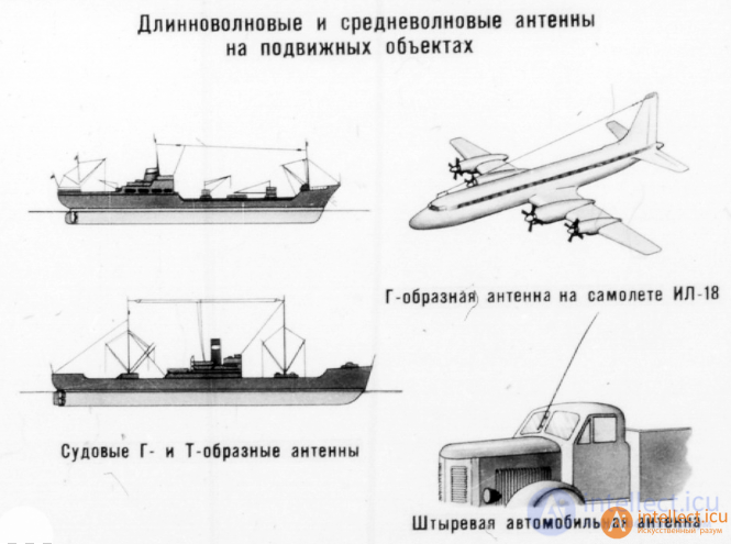
LONG WAVES. Waves of this range are called long, because their low frequency corresponds to a large wavelength. They can spread over thousands of kilometers, as they are able to go around the earth's surface. Therefore, many international radio stations broadcast on long waves.
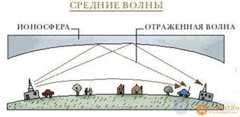
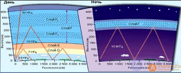
MEDIUM WAVES do not propagate over very large distances, since they can only be reflected from the ionosphere (one of the layers of the Earth’s atmosphere). Medium-wave transmissions are better received at night when the reflectivity of the ionosphere layer increases
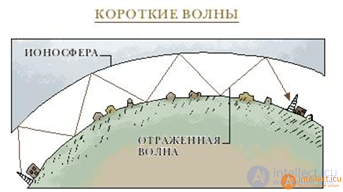
SHORT WAVES are repeatedly reflected from the Earth's surface and from the ionosphere, due to which they propagate over very large distances. Gears
shortwave radio stations can be received on the other side of the globe.
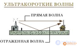
ULTRA-SHORT WAVES (VHF) can be reflected only from the surface of the Earth and therefore are suitable for broadcasting only at very small distances. On the VHF waves, stereo sound is often transmitted, since interference is weaker on them.
In a homogeneous medium, radio waves propagate rectilinearly. However, the atmosphere is a heterogeneous environment. At different distances from the transmitting radio station, pressure, temperature, density, humidity and other atmospheric parameters are different.
Under the influence of solar and cosmic radiation, free electrons are released from the atoms of the gases that make up the atmosphere, and the atoms turn into positive ions. This process is called ionization. Most of the ions are contained in the upper layer of the atmosphere - the ionosphere, located at a distance of 50 ... 80 km from the surface of the Earth. The speed of propagation of radio waves in environments with different electrical properties is not the same. This leads to the fact that during the transition from one medium to another they are refracted, i.e., the direction of propagation of radio waves changes.
The radio waves emitted by the antenna propagate along the earth's surface (surface waves) and at an angle to the horizon (spatial waves) - Fig. 4.6. Surface radio waves envelope objects well if the dimensions of the latter are less than the wavelength. When receiving signals from radio stations operating in the long wavelength range, the energy of surface waves is mainly used. But the energy of long surface waves is absorbed by the Earth’s surface, so as you move away from the station, the volume of reception of its transmissions decreases until it disappears completely. To increase the range of such a radio station, the power of its transmitter is increased.
Medium waves are worse around the various irregularities of the earth's surface and are absorbed more strongly. In this regard, at the same transmitter powers, the distance at which the reliable transmission of the long-wave radio station is carried out is greater than the medium-wave one.
The main advantage of surface radio waves is that a stable radio communication is provided within their limits.
Not all the energy of electromagnetic waves emitted by an antenna of a radio station is transferred by surface radio waves, part of it creates spatial radio waves, which, having reached the ionosphere layer, are refracted towards the Earth. The degree of refraction depends on the density of ionized atoms of the gas, the angle of incidence of the spatial wave and its length; the longer the radio wave, the stronger it is refracted.
Spatial radio waves of the long wavelength range are refracted in the lower layers of the ionosphere, and the direction of their propagation in these layers changes so much that they again go to the Earth, as if reflected from the ionosphere. Spatial radio waves can enter an area where surface radio waves do not reach. Thanks to this, you can listen to the broadcasts of a radio station operating in the Far East, a range in an area that surface radio waves do not reach. Between the reception zones of surface and spatial radio waves there is an area in which there is no signal reception of a working radio station. It is called the "dead" zone, or the zone of silence.
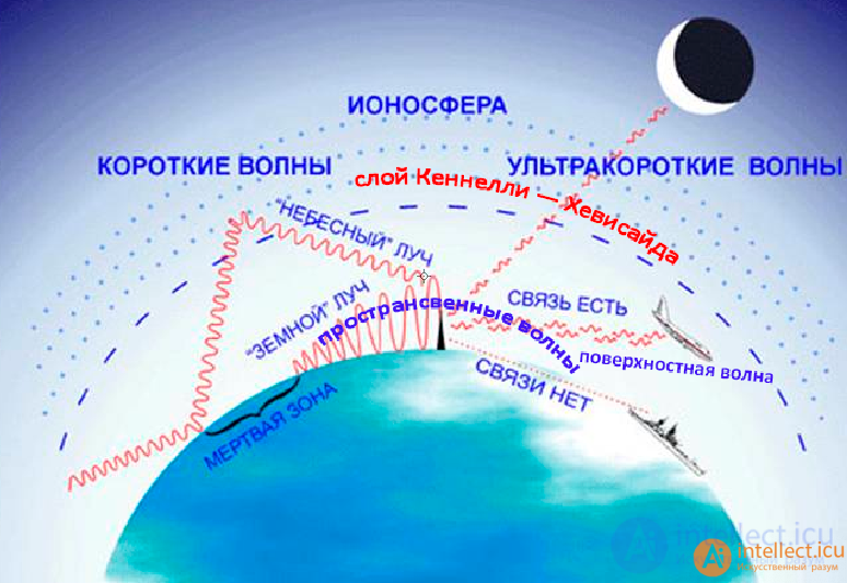
Fig. 4.6. Radio wave propagation
Spatial radio waves of the SW range penetrate deeper into the ionosphere than long waves, and as a result of which they are more strongly attenuated. During the day it is so significant that radio communication in the CB range can only be carried out using surface waves. With sunset, the ionization of gas atoms decreases, and weakens. attenuation of spatial waves. Here: why at night the NE band is almost completely “clogged” with working radio stations, and during the day only close or powerful radio stations are heard in this range.

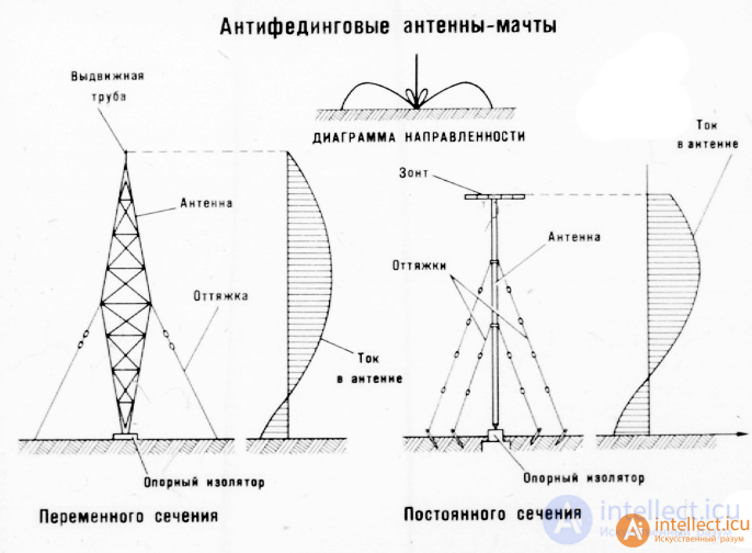
mast anti-fading antennas
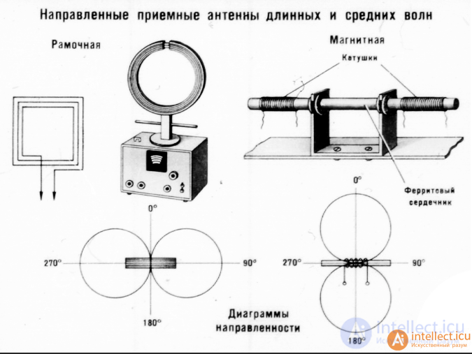
directional receiving antennas of long and medium radio waves
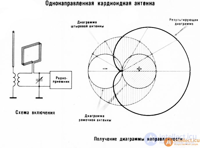
unidirectional cardioid antenna and receiving radiation patterns

shortwave antennas
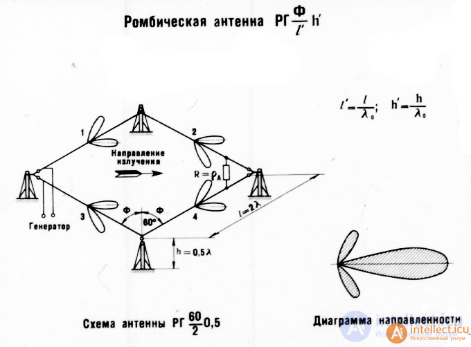
rhombic antenna
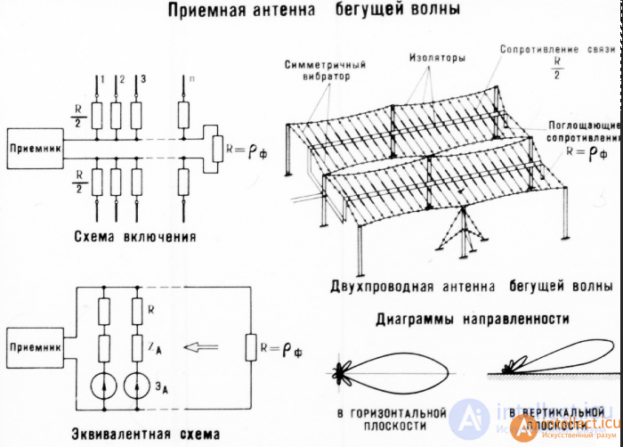
traveling wave receiving antenna
A traveling wave antenna (abbrev. ABV ) is a directional antenna along the geometric axis of which a traveling wave of electromagnetic waves propagates.
A traveling wave is a wave motion in which the surface of equal phases (phase wave fronts) moves with a finite speed (constant for a homogeneous medium). Examples are elastic waves in a rod, a column of gas or liquid, an electromagnetic wave along a long line or in a waveguide
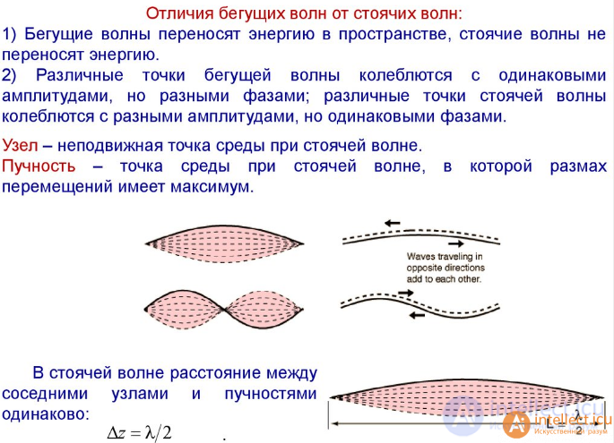
difference between traveling and standing radio waves
Unlike standing waves, traveling waves, when propagating in a medium, carry energy. A traveling wave, the group velocity of which is nonzero, is associated with the transfer of energy, momentum, or other characteristics of the process
The ABC can be performed in two types: from discrete (separate) emitters located along the axis at some distance from each other or in the form of a single solid emitter, which is located in the direction of the radiation / reception axis. In the second case, a solid emitter is considered as the sum of discrete emitters adjacent to one another.
Antennas of the first type include:
Antennas of the second type include:
The ABV has maximum radiation (reception) in the direction of its axis. For communication between two objects on the ground - the axis of the emitter is usually directed parallel to the surface of the earth on a straight line connecting two objects.
Coefficient of directional action of the ABC D = kL / l, where L is the antenna length, l is the wavelength, k is a coefficient depending on the direction of action of an individual emitting element, traveling wave value, ratio of amplitudes of currents of radiating elements, etc. The value of k usually lies in the limits of 4-8. The directional action coefficient is maximum when the phase velocity v of the traveling wave is slightly lower than the speed of light with and equal to
v = c-2l (2L + l).
The first characteristic property of ABC is the shape of the spatial radiation pattern with axial symmetry. That is, regardless of the plane passing through the axis of the emitter, the shape of the diagram is the same.
The second characteristic property is a satisfactory direction of action (in most ABCs ), which remains in a wide range of waves. The first property is manifested the more, the greater the L / l ratio and the higher the axial symmetry of the radiation pattern of each radiating element.
In practice, ABA is used in receiving and transmitting radio devices at all radio wavelengths.
For example, helical antennas are used to receive / transmit high-frequency signals in devices such as cell phones.
Antennas of the wave channel type are used for receiving television, radar and amateur radio signals.
Beverage antennas are used to provide communications in the armed forces, since, unlike simple whip antennas on portable radios, they can significantly increase the range of signal reception / transmission
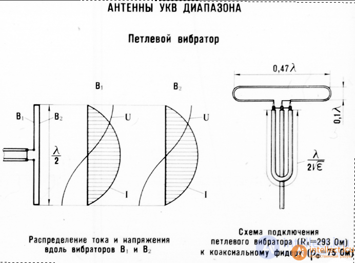
VHF antennas
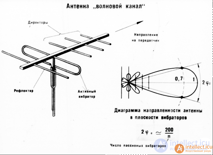
antenna wave channel

microwave antennas with a radiating surface
Phased Antenna Array ( PAR ) - an antenna array [1], the radiation direction and (or) the shape of the corresponding radiation pattern of which are regulated by changing the amplitude-phase distribution of currents or excitation fields on the radiating elements [2].
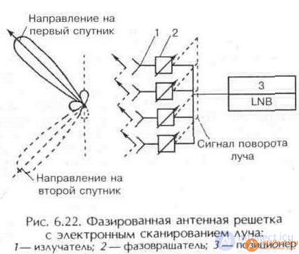
A radiating element (antenna array) is a component of an antenna array, an antenna or a group of antennas with a given relative excitation [2]. In the antenna array, the desired radiation pattern is formed due to a specially organized interference of electromagnetic waves emitted into space by its radiating elements. To do this, they provide the necessary amplitude-phase distribution — the necessary relative amplitudes and initial phases of alternating currents or excitation fields of each radiating element of the antenna array. The difference between the phased array antenna is that the amplitude-phase distribution is not fixed, it can be regulated (controlled change) during operation [2]. Due to this, it is possible to move the beam (main lobe of the radiation pattern) of the antenna array in a certain sector of space (the antenna array with electric beam scanning [3] as an alternative to an antenna with mechanical scanning, that is, an alternative to a mechanically rotating antenna [4]) or change the shape of the radiation pattern.
These and some other properties of the headlamps, as well as the ability to use modern automation and computer technology to control the headlamps, have made them promising and widely used in radio communications, radar, radio navigation, radio astronomy, etc. Headlamps containing a large number of controllable elements are included the composition of various ground (stationary and mobile), ship, aviation and space radio systems. Intensive development is underway in the direction of further development of the theory and technology of PAR and to expand the scope of their application
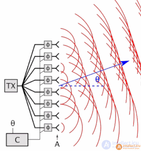
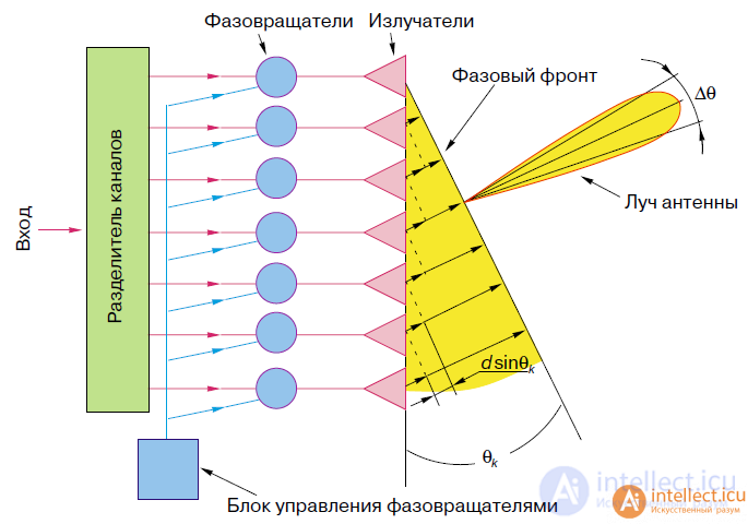
The principle of operation of a phased array antenna
An antenna array of N radiating elements allows you to increase approximately N times the directional coefficient (KND) and, therefore, the antenna gain compared to a single emitter, as well as narrow the beam to increase noise immunity, resolution in angular coordinates, and the accuracy of direction finding of radio emission sources in radar and radio navigation.
An example of the use of weakly directed emitters can be called antennas of base stations of the GSM standard, where patch antennas are used as emitters. As emitters of LTE standard antennas, dipoles and monopoles are used [7].
An interesting example of the use of directional antennas in the configuration of antenna arrays is the Allen Telescope Array project, which uses mirror antennas as elements of the antenna array for radio telescopy.
According to the method of changing the phase shifts, the PAR is distinguished:
The headlights with electric scanning have the greatest potential. [ Source not specified 254 days ] They provide the creation of a variety of phase shifts throughout the opening and a significant rate of change of these shifts with relatively small power losses. Ferrite and semiconductor phase shifters (with a speed of the order of microseconds and power losses of ~ 20% [ source not specified 254 days ]) are widely used on microwave in modern phased arrays. The operation of the phase shifters is controlled by a high-speed electronic system, which in the simplest cases controls groups of elements (for example, rows and columns in flat headlights with a rectangular arrangement of emitters), and in the most complex ones, each phase shifter individually. The beam can be swung in space both according to a predetermined law, and according to a program developed during the operation of the entire radio device, which includes the PAR.
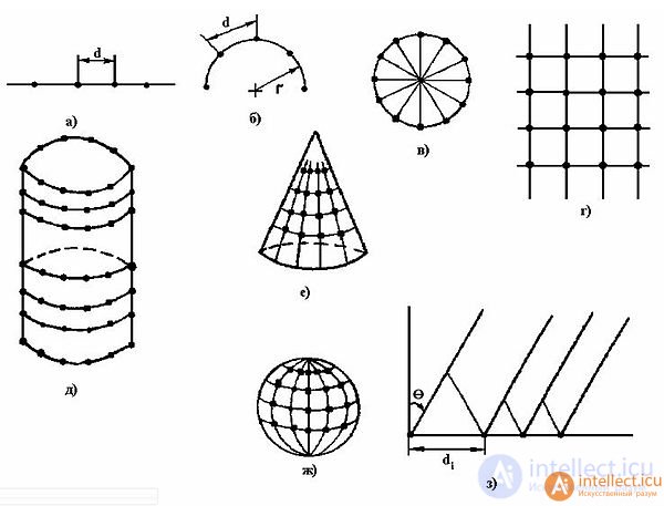
Classification of antenna arrays; a) linear; b) arc; c) ring; g) flat; e) cylindrical; e) conical; g) spherical; h) non-equidistant
Antenna arrays can be classified according to the following main features:
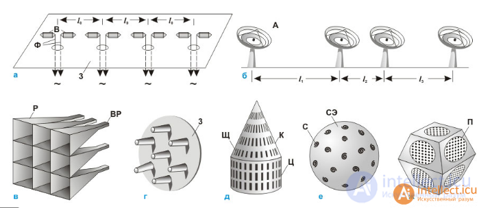
Structural diagrams of some phased array antennas (PAR) -
linear equidistant with symmetrical vibrators and a common mirror (a);
linear non-equidistant with full-rotated specular parabolic antennas (b);
flat with a rectangular arrangement of horn emitters (c);
flat with a hexagonal arrangement of dielectric rod emitters (g);
conformal with slot emitters (d);
spherical with spiral emitters (e);
flat phased array antenna systems (g);
In - vibrators; Ф - excitation lines (feeders); Z - conductive mirror (reflector); A - mirror antennas; P - horns; BP - exciting radio waves; E - a metal screen; Щ - slot emitters; K - conical HEADLAMP; C - cylindrical headlight; C - spiral emitters; SE - spherical screen; P - flat phased antenna arrays (dots indicate radiators); L0 is the distance between B; l1, l 2, l3 - distances between A.
Areas of Example
space radio communications. eg Starlink project
radar
mobile connection
Surgical Ultrasound Phased Arrays
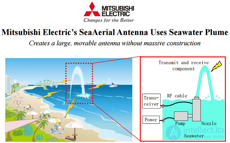
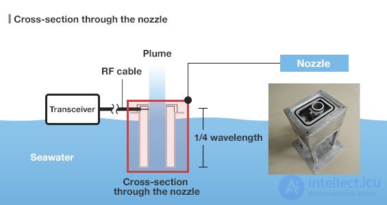
Sea water is a hundred times more efficient conductor of electricity than fresh water. Theoretically, this is sufficient to construct a primitive antenna for receiving and transmitting radio waves. However, in fact seawater is inferior to metals in conductivity by about a million times.
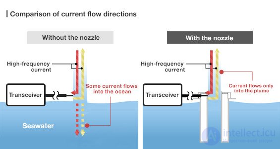
This did not prevent the Japanese company Mitsubishi from calculating the optimum diameter of the jet of water supplied under pressure to the antenna nozzle, and to design the SeaAerial system. Its efficiency is about 70%. During the tests, a small SeaAerial model successfully caught the TV signal.
From a practical point of view, the new invention solves serious problems. Mitsubishi engineers indicate that the low-frequency signals used to communicate warships and submarines require very large antennas that can reach several tens of meters in height. As it is extremely difficult to erect such structures in the open sea from concrete and metal, they could be replaced by structures made of water jets, it is noted in a press release.

Comments
To leave a comment
Microwave Devices and Antennas
Terms: Microwave Devices and Antennas