Lecture
In the centimeter range, the implementation of coaxial and strip filters becomes difficult due to the small size of the filter elements and tight tolerances. The use of waveguide transmission lines to build filters allows you to get the best electrical performance.
Currently, there are many types of waveguide filters. The most widespread are stripline filters on volume resonators with quarter-wave and direct connections between resonators, corrugated filters (filters on segments of transmission lines with high and low wave resistance and variable length) and filters on resonant diaphragms.
Below is the calculation and design of the listed types of bandpass filters.
Filters on volumetric resonators are usually used in the design of narrow-band filters with a bandwidth of not more than 10%. The cavity resonator is a segment of a waveguide of length l , bounded on both sides by two inhomogeneities (jB). Such a resonator will behave like any noise circuit. Most clearly this can be imagined as follows. If non-uniformity is placed in the waveguide, for example, an inductive pin, then at a certain distance from this pin (non-uniformity) the input resistance will have a capacitive character with the same reactivity value and active component equal to the wave resistance. If an inductive probe is placed in this section again, it will compensate for the reactive component of the input resistance and the system will be non-reflective at the frequency in question. The resonance condition of such a resonator:
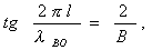 (4.88)
where l is the length of the resonator;
B — normalized conductivity of inhomogeneities;
l in - the resonant wavelength in the waveguide.
To increase the selectivity of the filters, several series-connected resonators are used. Depending on the method of connecting the resonators, filters with a quarter-wave and direct connections differ. The quarter-wave coupling method is based on the property of segments l = l / 4 to transform the load resistance in accordance with the ratio
 (4.89)
where r 0 is the wave drag of the sticky;
Z H - load resistance.
Therefore, if the load resistance consists of a series resonant circuit, then at the input of a quarter-wave line, the admittance is equal to the admittance of the tuned parallel circuit. If the load resistance is a parallel circuit, then the quarter-wave line transforms it into a serial circuit (Fig. 4.11).
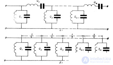
Fig. 4.15. Representation of a multi-link circuit by parallel contours located across quarter-wave segments.
This property of the quarter-wave line makes it possible to present the equivalent circuit of the filter with a ladder diagram of a conventional low-pass filter (Fig. 4.15).
Resonator filters with l / 4 couplings are applied with a bandwidth of less than 1%. In such filters, to obtain a given bandwidth, lower reactive conductivities of the bonds are required than in filters with direct coupling, which leads to looser tolerances for the manufacture of filters.
For broadband filters (with a bandwidth of more than 1%), the best is the filter with direct coupling between the resonators. When using filters with direct connections, the length of the filter is much shorter than the filter with quarter-wave connections.
For the calculation of filters with l / 4 and direct connections, a synthesis method using a prototype low-pass filter is used.
Regardless of whether l / 4connection is used or direct, quarter-wave transformers (resistance inverters) are included in the calculation, with which the equivalent filter circuit can be represented by a ladder bandpass filter circuit. In the case of direct connections, resistance transducers are short segments of lines with reactivity included.
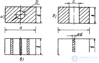
Fig. 4.17. Practically used inductances for waveguides: a - a round hole in a continuous partition; b - symmetric diaphragm; in the three pins; d is a single pin in the center of the waveguide.
As inhomogeneities (coupling elements) inductive diaphragms, pins, capacitive diaphragms can be used. Inductive coupling elements are used more often, since they are relatively easy to make and less critical to tolerances compared to capacitive elements. Practically, four forms of inductances are used, which are shown in fig. 4.17. The physical configuration of the coupling inductances determines the unloaded Q of the resonator. Communication through a round hole (Fig. 4.17, a) allows you to get the highest Q o . The connection made by a single pin gives the smallest value of Q o .
The simplest to manufacture are filters that use inductive pins, which make it possible to abandon the expensive milling work required to create grooves when installing the orifices in the waveguide. Soldering the pins is much easier than soldering the diaphragms. The pins do not overlap the internal cavity of the pipe, which allows you to visually monitor the quality of the internal surface of the pipe and the soldering process. Therefore, filters on inductive pins are most common. To increase the Q o of the resonators, multi-pin structures are used: two-, three-, four-pin, more often one-and three-pin structures are used.
For the selected type of inhomogeneities and for the known value of the normalized conductivity, their geometrical dimensions are determined.
For one-pin construction (Fig. 4.17, g)
 (4.93)
where a is the size of the wide wall of the waveguide;
B - normalized conductivity of heterogeneity;
 i = 0.1 ... N ,
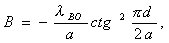
d - diameter of the pin. For a three-pin design (Fig. 4.17, b) with a symmetrical arrangement of the pins at a distance of a / 4
 (4.94)
where r is the radius of the pin;
a is the size of the wide wall of the waveguide;
l 0 - the average wavelength of the bandwidth in the air.
The given types of communication can be used when d / a << 0.08 .
For large values of d , the effect of the longitudinal impedances of the pins begins to show, which makes it impossible to obtain the desired characteristics. For the implementation of heterogeneities with large B , other types of connections are used (Fig. 4.17, a, 6 ) .
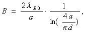
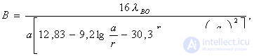
For communication in the form of a round hole (Fig. 4.17, a)
 (4.95)
where a is the size of the wide wall of the waveguide;
b is the size of the narrow wall of the waveguide;
D is the diameter of the connection hole.
For communication in the form of a rectangular window (Fig. 4.17, c)
 (4.96)
where d is the width of the communication hole. Formulas (4.95), (4.96) are valid when the diaphragm thickness is t << l 0 ( t @ 1 = 2 mm ) .
The selected type of discontinuity determines the design of the filter. An example of a filter design using triples and single pins is shown in fig. 4.18.
The above calculation method can be applied to the calculation of filters with quarter-wave connections using several additional transformations, as a result of which the prototype low-pass filter is converted into a stair bandpass filter (Fig. 4.2, d). Through the elements of the prototype of the low-pass filter, the loaded Q-factors of the contours of the band-pass filter are determined (Figure 4.15).

Fig. 4.18. The design of the three-resonator filter centimeter range.
The quality of the links are equal:
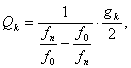 k = 1,2,3 ... N (4.97)
here g k - the corresponding elements of the prototype, defined by the formulas (4.9), (4.10) for filters with maximally smooth and Chebyshev characteristics, respectively;
f n is the upper frequency of the filter pass filter (Fig. 4.3).
According to known Q-factors, the normalized conductivities are determined by the formula
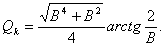 (4.98)
Further, the selection and calculation of the geometric dimensions of the inhomogeneities is performed as described for filters with direct links.
By the formula (4.92) are determined by the length of the resonators. The lengths of the connecting lines (the distance between the resonators) are determined using the equation
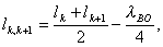 (4.99)
where k is the number of the resonator.
The geometrical dimensions of the inhomogeneities must be made according to the third accuracy class.
Corrugated filters are filters on segments of transmission lines with high and low characteristic impedance and variable length. The wave impedance difference is made by changing the narrow wall of the waveguide .
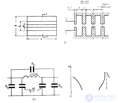
Fig. 4.19. Corrugated waveguide filter: a - design; b - equivalent circuit diagram; c - frequency response.
The width of the waveguide a remains constant (Fig. 4.19, a ). The lower border of the transparency band of a corrugated filter, determined by the critical frequency of the waveguide itself, has a small slope, therefore, these filters are usually used in the waveguide technique as low-pass filters. The equivalent filter link diagram and frequency response are shown in fig. 4.19 b.
The design of the corrugated filter is shown in Fig. 4.21.
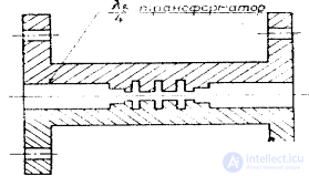
Fig. 4.21. The design of a corrugated waveguide filter.
It is a solid milled comb, connected to each other with pins and screws. The dimensions of the dies and the position of the pins must be maintained at accuracy class 3. The filter design provides for quarter-wave transformers to match the wave impedance of the filter with the wave impedance of a standard waveguide.
Filters on resonant diaphragms are widely used in the design of filters with a bandwidth of more than 10%. Waveguide filters on resonant diaphragms allow using the simplest method to implement the ladder bandpass filter scheme shown in fig. 4.2, by installing resonant diaphragms in the waveguide at a distance l B / 4 from each other (Fig. 4.23).
Each diaphragm is equivalent to the resonant branch of the circuit; quarter-wave distances between the diaphragms convert parallel branches into serial ones. To calculate filters on resonant diaphragms, the ladder L – C bandpass filter is used as a prototype (Fig. 4.2, d ), for the calculation of which the synthesis method is used.

Comments
To leave a comment
Microwave Devices and Antennas
Terms: Microwave Devices and Antennas