Lecture
Strip lines are the most convenient for designing microwave filters in the meter and decimeter ranges.

Fig.4.9 Elements of strip lines, equivalent to lumped elements: a - consistent inductance; b - sequential capacity; в - parallel capacity; g - parallel inductance.
The use of printed stripline allows you to get small and cheap filter designs . When creating filters on strip lines, the same methods are used as in designing filters on other types of transmission lines, that is, some simple line elements are used that are equivalent to concentrated reactivity. Elements of symmetric strip lines, which are widely used for designing microwave filters, are shown in fig. 4.9. Resonant elements can be made using l / 4 and l / 2 segments. Using the shown in fig. 4.9 elements, many filter schemes can be implemented.
A simple type K multi-stage low-pass filter can be designed using line segments with high characteristic impedance, equivalent to concentrated inductances, and open arms less than l / 4 in length , equivalent to capacitances.
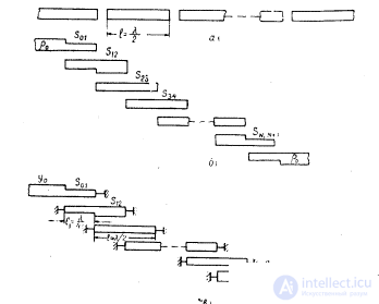
Fig. 4.10. Bandpass filter circuits on coupled resonators: a - with a “serial” connection; b - with a “parallel” connection with open resonators; in —with “parallel” coupling with short-circuited resonators.
The method of calculating the filter is similar to the method of calculating the coaxial low-pass filter given in § 4.2. To determine the geometrical dimensions of the segments with the required characteristic impedance, the graphs of fig. 1.4, 1.5.
Simple from a constructive point of view are the bandpass filter circuits on coupled resonators with a “serial” and “parallel” coupling (Fig. 4.10). Filters with a "parallel" connection (Fig. 4.10, b, c) are small-sized and simple in design, especially in the printed version; therefore, they are more widely used in microwave technology than filters with a "serial" connection between resonators. Filters with "parallel" coupling are open or short-circuited half-wave resonators with distributed electromagnetic coupling.
For analyzing filters on connected lines, the concepts of inverters (converters) of resistance (or conductance) are used. An ideal inverter has the property of a quarter-wave transformer to convert a parallel circuit into a serial circuit. With the help of resistance inverters equivalent circuit filter pa connected lines
can be represented by a conventional bandpass filter ladder scheme (Fig. 4.2), which is calculated according to the already known method.
The further development of filters on resonators with parallel coupling were filters on rod structures. Structurally, such filters are made in the form of a series of segments of conductors of the same length, arranged parallel to each other (Fig. 4.12). Conductors are placed between parallel grounded plates (symmetrical design). Each of the conductors has a short circuit at one end, and an idle at the other (fig. 4.12, a, b) or a capacitor connected between the ends of the conductor and grounded plates (fig. 4.12, c). Due to the distributed electromagnetic field, the connection between the conductors along their entire length is carried out. Filters on core structures are more compact, have better

Fig. 4.13. Formation of a quarter-wave resonator from half-wave:
a - half-wave; b - quarter wave .
electrical characteristics than filters with parallel connection (Fig. 4.10, b , c). Therefore, at present, in the microwave technology, when designing strip filters, filters on rod structures are mainly used. The filters shown in fig. 4.12, a, b, are called filters with counter rods. The filters shown in fig. 4.12, in - comb filters.
When designing filters with a bandwidth of less than 30%, it is advisable to use comb filters and filters with oncoming rods with short-circuited input lines (Fig. 4.12, a). When designing broadband filters (more than 30%), filters with counter rods with open input lines are used (Fig. 4.12. B ).
The theory of calculating filters, given in [9], is based on the equivalence between filters with parallel coupling and filters on rod structures. The equivalence of these schemes near the average frequency of the passband ( f 0 ) is evident from Fig. 4.13.
When calculating filters on rod structures, as well as for filters with parallel coupling, resistance inverters (conductivities) are used, through which first your own Cc / e , load C K S and mutual capacitances of С С , k + 1 / e, and then the geometric dimensions of the rods. Below is the method of calculating filters on rod structures according to specified requirements.
For convenience of calculations, the design process is divided into three stages:
Selecting a filter scheme and determining its main characteristics.
Determination of electrical parameters of the rod grid.
Determination of the geometric dimensions of the rod lattice.
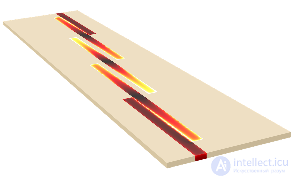
Модель Полосно-пропускающего фильтра на связанных линиях

Comments
To leave a comment
Microwave Devices and Antennas
Terms: Microwave Devices and Antennas